D-67
FX Series PLC User's Manual - Data Communication Edition
Computer Link
7 Commands
7.8 WT Command [Tests Device Memory in 1-Word Units (by Writing Arbitrarily)]
A
Common Items
B
N:N Network
C
Parallel Link
D
Computer Link
E
Inverter
Communication
F
Non-Protocol
Communication
(RS/RS2 Instruction)
G
Non-Protocol
Communication
(FX
2N
-232IF)
H
Programming
Communication
I
Remote
Maintenance
Apx.
Discontinued
models
2. Specification example
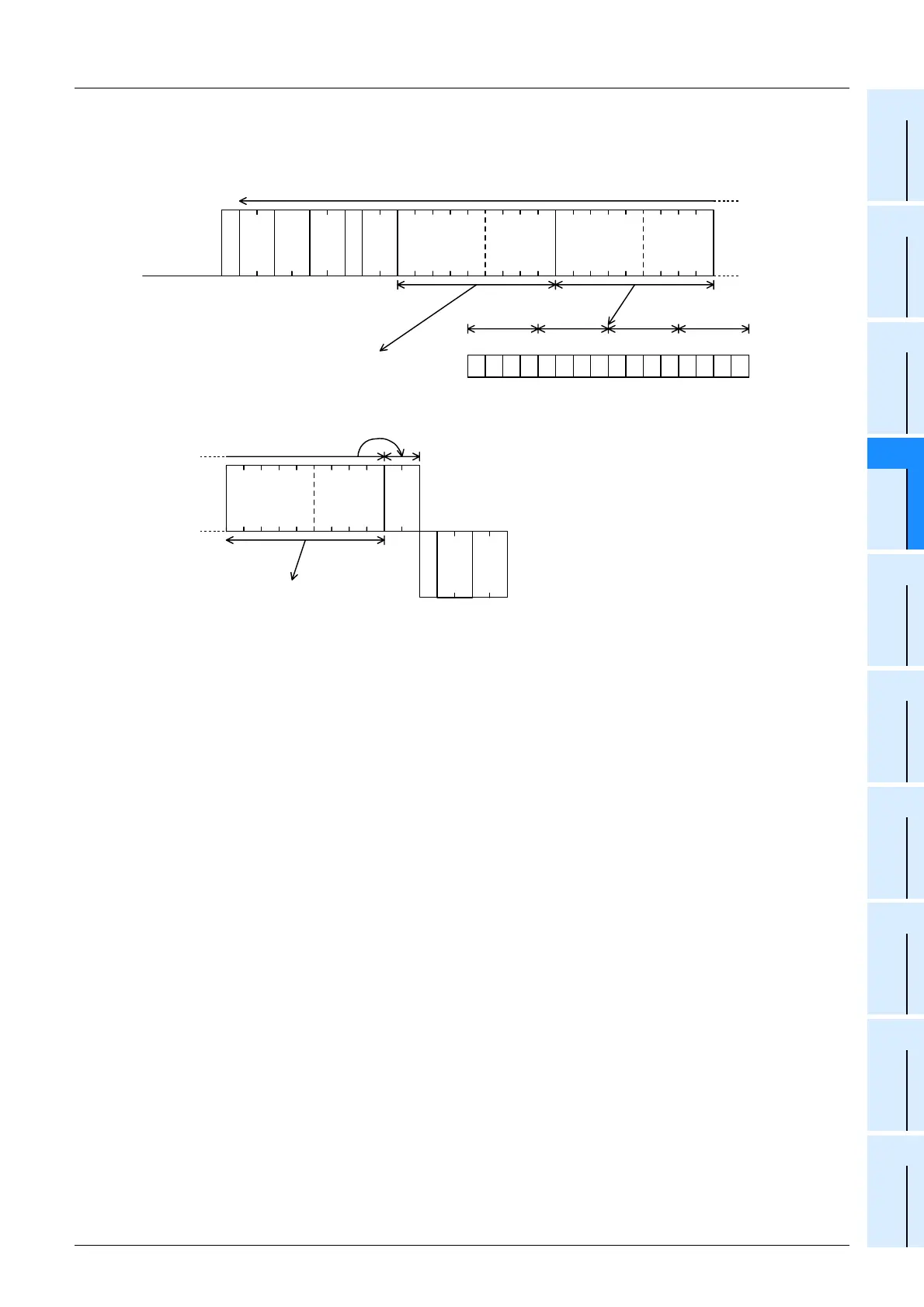
When writing data for setting the current value of D500 to "1234H", Y100 to Y117 to "BCA9H" and the current
value of C100 to "64H" in the PLC whose station number is 5 (while the message waiting time is set to 0 ms)
B C A 9D 0 5 0 0 1 2 3 4 Y 0 1 0 0
E
N
Q
0 5 F F W T 0 0 3
35
H
30
H
46
H
46
H
54
H
57
H
30
H
33
H
05
H
44
H
30
H
35
H
30
H
30
H
31
H
32
H
34
H
33
H
This range is regarded as the sum check target.
59
H
30
H
31
H
30
H
30
H
42
H
43
H
39
H
41
H
Indicates that "1234H (which is "4660"
in decimal)" is written to D500.
1 0 1 10110111 00001
BC 9A
Y
1
0
6
Y
1
0
7
Y
1
1
0
Y
1
1
1
Y
1
1
2
Y
1
1
3
Y
1
1
4
Y
1
1
5
Y
1
1
6
Y
1
1
7
Y
1
0
0
Y
1
0
1
Y
1
0
2
Y
1
0
3
Y
1
0
4
Y
1
0
5
Computer side
PLC side
Each bit is reset (OFF) in the case of "0", and
set (ON) in the case of "0".
A
C
K
0 5 F F
0 70 0 6 4C N 1 0 0
30
H
30
H
46
H
46
H
06
H
37
H
30
H
43
H
30
H
31
H
4E
H
30
H
30
H
30
H
34
H
36
H
Indicates that "64H (which is "100" in decimal)"
is written to the current value of C100.
This range is regarded as the
sum check target.
30
H
 Loading...


