G-29
FX Series PLC User's Manual - Data Communication Edition
Non-Protocol Communication (FX2N-232IF)
5 Creating Programs
5.4 Buffer Memory (BFM)
A
Common Items
B
N:N Network
C
Parallel Link
D
Computer Link
E
Inverter
Communication
F
Non-Protocol
Communication
(RS/RS2 Instruction)
G
Non-Protocol
Communication
(FX
2N
-232IF)
H
Programming
Communication
I
Remote
Maintenance
Apx.
Discontinued
models
5.4.18 Error code <BFM #29>
For the error codes, refer to Section 7.2.
5.4.19 Model code <BFM #30>
The model code of the 232IF is "K7030".
The model code is a specific code assigned to each special extension module. By reading the model code in
the PLC, the equipment type can be checked.
5.4.20 Number of bytes to be sent <BFM #1000>
Setting range: 0 to 512 bytes (when the buffer data length is 16-bit)
0 to 256 bytes (when the buffer data length is 8-bit)
This buffer specifies how many bytes should be sent among the 512 bytes/256 words in the 16-bit send data
buffer (BFM #1001 to 1256).
5.4.21 Send data buffer <BFM #1001 to 1256>
The send data buffer is a section of 16-bit buffers for storing the send data. The send data buffers can store
up to 512 bytes/256 words.
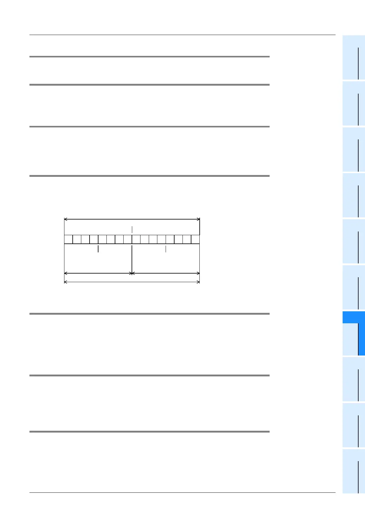
Structure of send/receive data buffer
Values in the send data buffers and receive data buffers are handled as hexadecimal values.
5.4.22 Number of received bytes <BFM #2000>
Stored value: 0 to 512+30
*1
bytes (when the buffer data length is 16-bit)
0 to 256+15
*1
bytes (when the buffer data length is 8-bit)
This buffer stores the number of bytes received from the external equipment. The value stored in this buffer is
cleared when the receiving complete flag reset command (BFM #1, b2) is given.
*1. "30" or "15" bytes are provided for the preliminary buffer in the interlink connection mode.
5.4.23 Receive data buffer <BFM #2001 to 2256>
The received data buffer is a section of 16-bit buffers for storing the data received from the external equipment.
The received data buffer can store up to 512 bytes/256 words.
The received data buffer structure is same as the send data buffer structure.
The contents of the received data buffer are cleared when the receiving complete flag reset command (BFM
#1, b2) is given.
5.4.24 Preliminary receive data buffer for interlink connection mode <BFM #2257 to 2271>
The preliminary receive data buffer is provided for storing the data beyond 512 bytes in the interlink
connection mode. The preliminary receive data buffers are used to receive the data sent after the receiving
enable (RS) signal is set to OFF until the external equipment suspends sending.
The contents of the preliminary receive data buffer are cleared when the receiving complete flag reset
command (BFM #1, b2) is given.
b15
3
0 0 1 1 0 0 1 0 0 1 0 0 0 0 0 1
Example: BFM #1001 (16-bit buffer)
b0
2
4 1
32
H
=2 41
H
=A
Highest-order byte Lowest-order byte
1 byte 1 byte
1 word
 Loading...


