11 Buffer Memory (Parameters & Monitored Data)
11.2 Servo Parameters
223
FX3U-20SSC-H Positioning Block User's Manual
11
Buffer Memory
12
Program
Example
13
Diagnostics
A
List of
Parameters and
Data
B
Version
Information
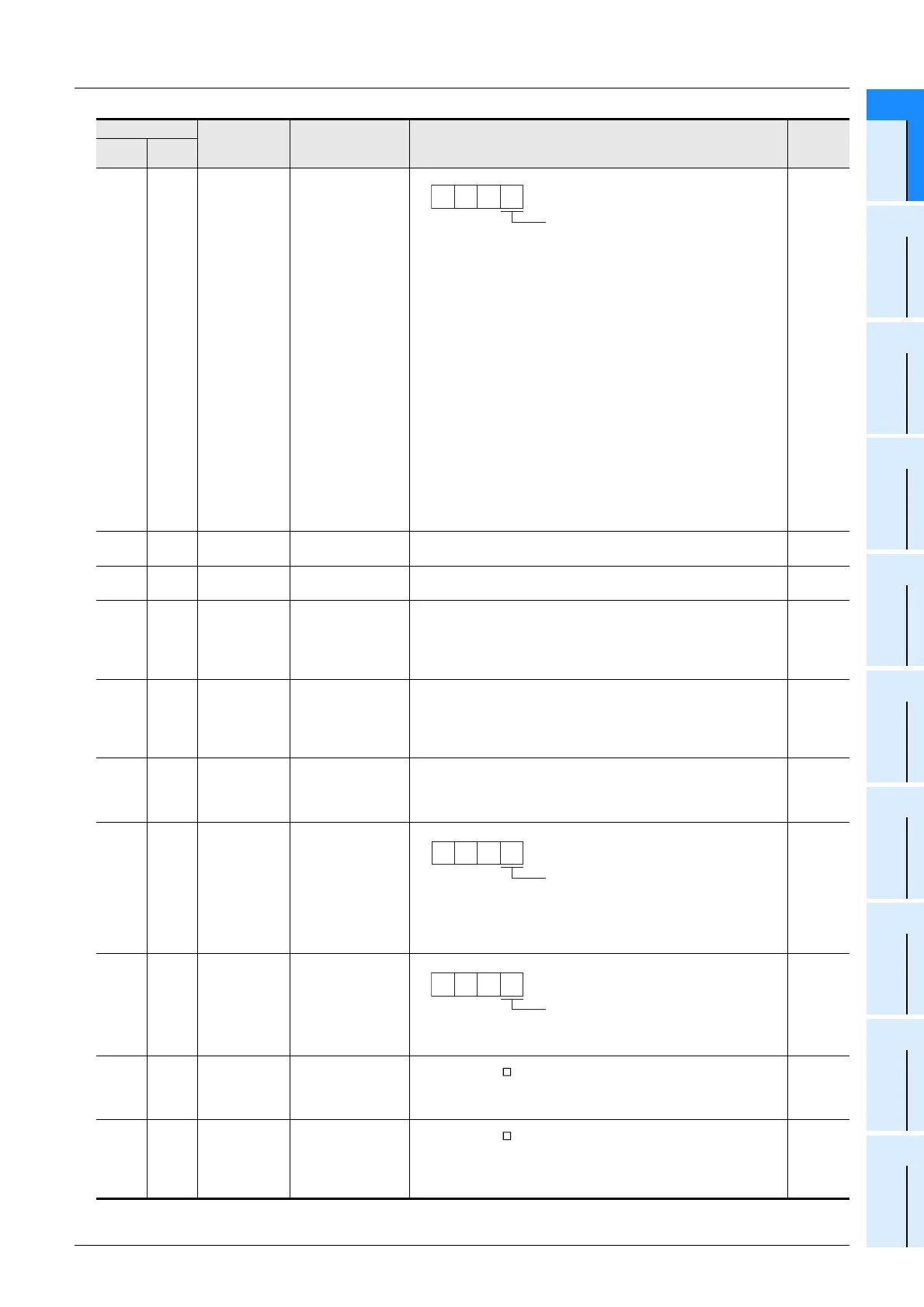
BFM
#15073
BFM
#15273
PC10
Analog monitor 2
output
Select a signal to be output to the analog monitor 2.
0: Servo motor speed (±8V at the maximum)
1: Torque (±8 V at the maximum)
*B
2: Servo motor speed (+8V at the maximum)
3: Torque (+8 V at the maximum)
*B
4: Current command (±8 V at the maximum)
5: Speed command (±8V at the maximum)
6: Droop pulses (±10 V/1 × 10
2
PLS)
*A
7: Droop pulses (±10 V/1 × 10
3
PLS)
*A
8: Droop pulses (±10 V/1 × 10
4
PLS)
*A
9: Droop pulses (±10 V/1 × 10
5
PLS)
*A
A: Feedback position (±10 V/1 × 10
6
PLS)
*A*C
B: Feedback position (±10 V/1 × 10
7
PLS)
*A*C
C: Feedback position (±10 V/1 × 10
8
PLS)
*A*C
D: Bus voltage (+8 V / 400 V)
*A: Encoder pulse unit
*B: Outputs 8 V as the maximum torque
*C: Can be used for the absolute position detection system
H0001
BFM
#15074
BFM
#15274
PC11
Analog monitor 1
offset
Set the offset voltage of the analog monitor 1 (MO1) output.
Setting range: -999 to 999 mV
K0
BFM
#15075
BFM
#15275
PC12
Analog monitor 2
offset
Set the offset voltage of the analog monitor 2 (MO2) output.
Setting range: -999 to 999 mV
K0
BFM
#15076
BFM
#15276
PC13
Analog monitor
feedback position
output standard data
Low
(Ver.1.40 or later)
Set the standard position of feedback output with analog monitor 1
(MO1) or 2 (MO2).
Setting range: -9999 to 9999 PLS
K0
BFM
#15077
BFM
#15277
PC14
Analog monitor
feedback position
output standard data
High
(Ver.1.40 or later)
Set the standard position of feedback output with analog monitor 1
(MO1) or 2 (MO2).
Setting range: -9999 to 9999 (× 10000PLS)
K0
BFM
#15080
BFM
#15280
PC17
Function selection
C-4
Select the home position setting condition in the absolute position
detection system.
0: Need to pass motor Z-phase after power on
1: Not need to pass motor Z-phase after power on
K1
BFM
#15083
BFM
#15283
PC20
Function selection
C-7
(Ver.1.40 or later)
Setting when undervoltage alarm occurs
0: Waveform of power supply voltage is not distorted
1: Set “1” if undervoltage alarm occurs because of distorted power
supply voltage waveform when using power regenerative converter
or power regeneration common converter
H0000
BFM
#15084
BFM
#15284
PC21
Alarm history clear
(Ver.1.40 or later)
Used to clear the alarm history.
0: Disable
1: Enable
H0000
BFM
#15087
BFM
#15287
PC24
Forced stop
deceleration time
constant
(Ver.1.40 or later)
Only the MR-J3- BS
Set deceleration time constant for forced stop deceleration.
Setting range: 0 to H1FFF
H0000
BFM
#15094
BFM
#15294
PC31
Vertical axis freefall
prevention
compensation
amount
(Ver.1.40 or later)
Only the MR-J3- BS
Set the compensation amount of the vertical axis freefall prevention
function.
Setting range: HF63C to H09C4 REV
H0000
BFM Number Servo
Amplifier
Parameter No.
Name Description Default
X-axis Y-axis
Analog monitor 2 (MO2) output selection
000
Setting when undervoltage alarm occurs
000
Alarm history clea
000

 Loading...


