6 Memory Configuration and Data Operation
6.2 Data Transfer Process
40
FX3U-20SSC-H Positioning Block User's Manual
6.2.3 Transfer (writing) servo parameters to servo amplifier
When the power is turned ON or when the system is reset
*1
, the 20SSC-H transfers servo parameters stored
in the flash memory to the buffer memory.
When the servo series (BFM #15000, #15200) is set to the connected servo amplifier, the 20SSC-H transfers
servo parameters to the servo amplifier.
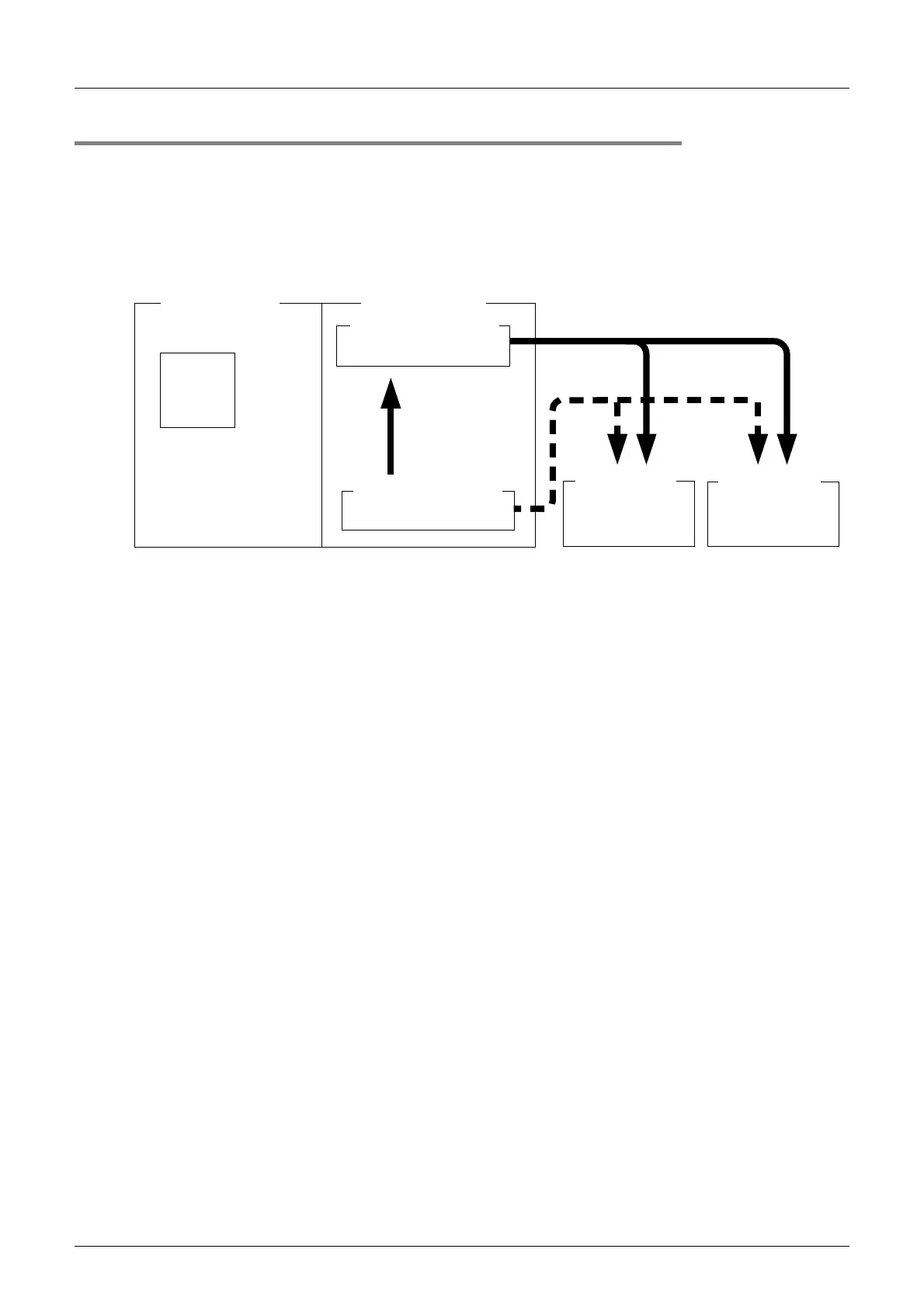
The figure below shows how to transfer servo parameters to the servo amplifier.
→ For the parameter setting, refer to Section 7.1
• How to transfer the servo parameters stored in the flash memory to the servo amplifier
→ For the parameter setting, refer to Section 7.1
Procedure (Transfer sequence: 1) and 2) in the above figure)
Store, in the flash memory, the servo series [BFM #15000 (X-axis) and #15200 (Y-axis)] set to the
connected servo amplifier series and the servo parameter transfer mode (b15) set to OFF in the
operation parameter 2 [BFM #14002 (X-axis) and #14202 (Y-axis)].
After turning the power ON or after executing the system reset command
*1
, the following events occur:
(Turn ON the power to the amplifier first, and then to the 20SSC-H (including the PLC).)
1) The 20SSC-H transfers the data stored in the flash memory to the buffer memory.
2) The 20SSC-H transfers the data (servo parameters) stored in the flash memory to the servo amplifier.
• How to transfer the servo parameters set in the sequence program to the servo amplifier
(The 20SSC-H Ver. 1.10 or later supports this method.)
→ For the parameter setting method, refer to Section 7.1
Procedure (Transfer sequence: a) and b) in the above figure)
Stores, in the flash memory, the servo series [BFM #15000 (X-axis) and #15200 (Y-axis)] set to any value
other than the connected servo amplifier series and the servo parameter transfer mode (b15) set to ON in
the operation parameter 2 [BFM #14002 (X-axis) and #14202 (Y-axis)].
After turning the power ON or executing the system reset command
*1
, the following events occur:
(Turn ON the power to the amplifier first, and then to the 20SSC-H (including the PLC).)
a) The 20SSC-H transfers the data stored in the flash memory to the buffer memory.
Next, use the sequence program sets the servo amplifier series connected to the servo series
[BFM #15000 (X-axis) and #15200 (Y-axis)].
b) The 20SSC-H transfers the data (servo parameters) stored in the buffer memory to the servo
amplifier.
*1. Only supported by 20SSC-H Ver. 1.10 or later. For details on system reset, refer to the following:
→ Refer to Subsection 7.9.12
Sequence
- Servo parameters
- Servo parameters
Power ON or
system reset
*
1
1), a)
b)
2)
FX
3U/FX3UC PLC
FX
3U
-20SSC-H
Buffer memory (BFM)
Flash memory (ROM)
Servo amplifier Servo amplifier
- Servo parameters
- Servo parameters
program

 Loading...


