12 Program Example
12.3 Explanation of Operation
257
FX3U-20SSC-H Positioning Block User's Manual
11
Buffer Memory
12
Program
Example
13
Diagnostics
A
List of
Parameters and
Data
B
Version
Information
12.3 Explanation of Operation
This section describes operation of the example program.
Positioning control parameters are used with their default settings.
→ For details on device assignments, refer to Section 12.2
→ For details on sequence programs, refer to Section 12.4
Note
• Set the servo series in the servo parameters according to the servo amplifier to be used.
→ Refer to Section 7.1 and 11.2
• Set the following parameters if necessary.
→ For details, refer to Section 7.1 and Chapter 11
- Function selection (C-4) for servo parameters
- Zero return interlock setting in positioning parameters
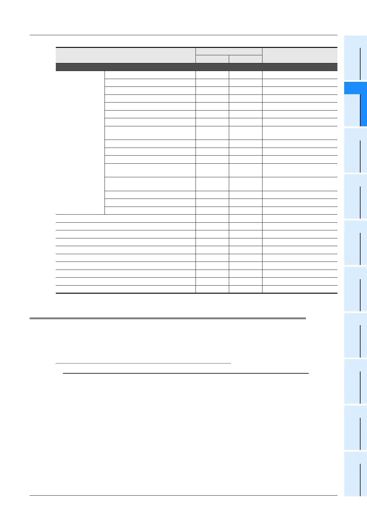
Monitor data
Status information
READY M40 M140
During forward rotation pulse output M41 M141
During reverse rotation pulse output M42 M142
Zero return completed M43 M143
Current value overflow M44 M144
Error occurrence M45 M145
Positioning completion M46 M146
Standby for remaining travel distance
at STOP
M47 M147
m code ON M48 M148
Unit ready M49 M149
During servo parameters transfer M50 M150
Saving to flash memory M51 M151
Use M51 for both the X-axis and
the Y-axis.
Initializing buffer memory M52 M152
Use M52 for both the X-axis and
the Y-axis.
During operation speed change M53 M153
During target address change M54 M154
During table operation execution M55 M155
Current address (user) D1, D0 D101, D100
Error BFM No. D6 D106
m code No. D9 D109
Operation speed present value D11, D10 D111, D110
Number of the table in operation D16 D116
Error code D29 D129
Motor rotation speed D53, D52 D153, D152
Servo status D64 D164
Servo warning code D68 D168
Motor feedback position D71, D70 D171, D170
Name
Device No.
Remark
X-axis Y-axis

 Loading...


