7 Before Starting Positioning Operation
83
FX3U-20SSC-H Positioning Block User's Manual
1
Introduction
2
System
configuration
3
Example
Connection
4
Installation
5
Wiring
6
Memory
configuration
and data
7
Before starting
positioning
control
8
Manual control
9
Positioning
Control
10
Table Operation
7.3 Handling the Forward Rotation Limit and Reverse Rotation Limit
7.3.1 Forward rotation limit 2 (FLS) and reverse rotation limit 2 (RLS)
[Servo amplifier limit]
Connect forward rotation limit 2 (FLS) and reverse rotation limit 2 (RLS) to the upper stroke limit (FLS) and
lower stroke limit (RLS) external signal terminals of the servo amplifier, respectively. This limit switch should
be provided in a position to avoid causing damage to the machine after activation.
→ For sudden stop performed when the stroke limit switch turns ON in the servo amplifier,
refer to Section 7.5
→ For parameters, control data and monitor data, refer to Chapter 11
1. Wiring the forward rotation limit 2 (FLS) and reverse rotation limit 2 (RLS)
Connect forward rotation limit 2 (FLS) and reverse rotation limit 2 (RLS) to the upper stroke limit (FLS) and
lower stroke limit (RLS) external signal terminals of the servo amplifier, respectively.
→ For terminal names and wiring in the servo amplifier, refer to the servo amplifier manual
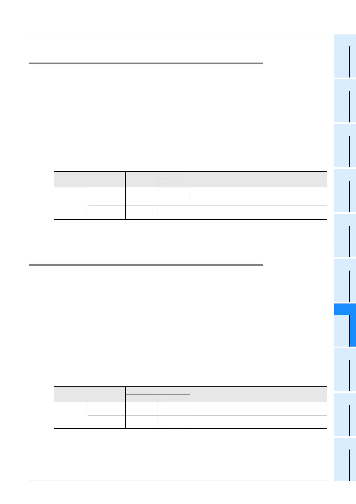
2. Servo amplifier external signal setting
Set the external input selection (positioning parameter) as follows.
→ For details, refer to Subsection 11.1.20
3. Restarting method
Refer to the following.
→ Refer to Section 7.3 (on the previous page)
7.3.2 Forward rotation limit 1 (LSF) and reverse rotation limit 1 (LSR) [PLC side limit]
Control the operation command 1 of the 20SSC-H using a sequence program.
Provide at a position so that activation is caused before forward rotation limit 2 or reverse rotation limit 2
connected to the servo amplifier.
→ For sudden stop operation performed when the rotation limit switch turns ON, refer to Section 7.5
→ For parameters, control data and monitor data, refer to Chapter 11
1. Wiring the forward rotation limit 1 (LSF) and reverse rotation limit 1 (LSR)
Connect forward rotation limit 1 (LSF) and reverse rotation limit 1 (LSR) at the input terminals of the PLC.
For details on the PLC wiring method, refer to the following respective PLC manual.
→ Refer to the FX3U Hardware Manual
→ Refer to the FX3UC Hardware Manual
2. Specifying forward rotation limit 1 (LSF) and reverse rotation limit 1 (LSR)
Operate the forward rotation limit 1 (LSF) and reverse rotation limit 1 (LSR) connected with the PLC with the
forward rotation limit flag and reverse rotation limit flag in Operation command 1, respectively.
→ For the operation command 1, refer to Subsection 11.4.10
→ For program examples, refer to Chapter 12
3. Restarting method
Refer to the following.
→ Refer to Section 7.3 (on the previous page)
BFM Number
Description
X-axis Y-axis
External input
selection
Selection of FLS/
RLS signal
BFM #14044
b0
BFM #14244
b0
Select "Use the forward rotation limit and reverse rotation limit in the
servo amplifier and PLC."
(Set b0 to ON.)
Logic of FLS/
RLS signal
BFM #14044
b8
BFM #14244
b8
Select "N/C contact (servo amplifier)."
(Set b8 to ON.)
BFM Number
Description
X-axis Y-axis
Operation
command 1
Forward rotation
limit (LSF)
BFM #518 b2 BFM #618 b2
Set this to perform a deceleration stop while outputting pulses for
forward rotation.
Reverse rotation
limit (LSR)
BFM #518 b3 BFM #618 b3
Set this to perform a deceleration stop while outputting pulses for
reverse rotation.

 Loading...


