11 Buffer Memory (Parameters & Monitored Data)
11.2 Servo Parameters
219
FX3U-20SSC-H Positioning Block User's Manual
11
Buffer Memory
12
Program
Example
13
Diagnostics
A
List of
Parameters and
Data
B
Version
Information
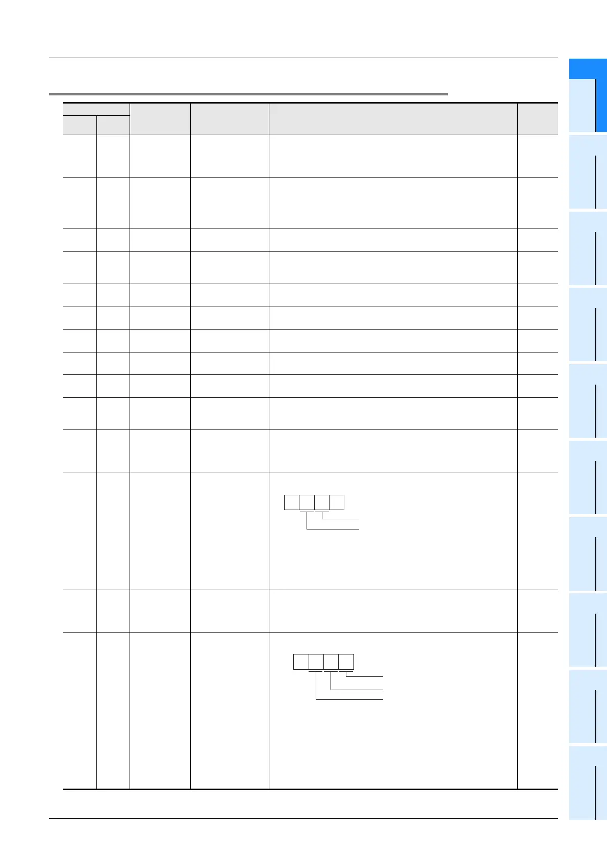
11.2.2 Servo parameters (Gain/Filter settings)
BFM Number Servo
Amplifier
Parameter No.
Name Description Default
X-axis Y-axis
BFM
#15019
BFM
#15219
PB01
Adaptive tuning
mode
(Adaptive filter 2)
Select the adaptive filter tuning mode.
0: Filter OFF
1: Filter tuning mode (adaptive filter)
2: Manual mode
K0
BFM
#15020
BFM
#15220
PB02
Vibration
suppression control
tuning mode
(advanced vibration
suppression control)
Select the vibration suppression control tuning mode.
0: Vibration suppression control OFF
1: Vibration suppression control tuning mode
2: Manual mode
K0
BFM
#15022
BFM
#15222
PB04 Feed forward gain
Set the feed forward gain coefficient to be used for positioning control.
Setting range: 0 to 100%
K0
BFM
#15024
BFM
#15224
PB06
Ratio of load inertia
moment to servo
motor inertia moment
Set the ratio of load inertia moment to servo motor inertia moment.
Setting range: 0 to 3000 (×0.1 times)
K70
BFM
#15025
BFM
#15225
PB07 Model loop gain
Set the response gain up to the target position.
Setting range: 1 to 2000 rad/s
K24
BFM
#15026
BFM
#15226
PB08 Position loop gain
Set the gain of the position loop.
Setting range: 1 to 1000 rad/s
K37
BFM
#15027
BFM
#15227
PB09 Speed loop gain
Set the gain of the speed loop.
Setting range: 20 to 50000 rad/s
K823
BFM
#15028
BFM
#15228
PB10
Speed integral
compensation
Set the integral time constant of the speed loop.
Setting range: 1 to 10000 (× 0.1 ms)
K337
BFM
#15029
BFM
#15229
PB11
Speed differential
compensation
Set the differential compensation.
Setting range: 0 to 1000
K980
BFM
#15030
BFM
#15230
PB12
Overshoot amount
compensation
(Ver.1.40 or later)
Set the control ratio against the friction torque.
Setting range: 0 to 100%
K0
BFM
#15031
BFM
#15231
PB13
Machine resonance
suppression filter 1
Set the notch frequency of the machine resonance suppression filter 1.
(Set the frequency in accordance with the mechanical resonance
frequency.)
Setting range: 100 to 4500 Hz
K4500
BFM
#15032
BFM
#15232
PB14
Notch shape
selection 1
Specify the notch shape used for the machine resonance suppression
filter 1 (Notch shape selection 1).
• Notch Depth Notch Width
0: Deep (-40db) 0: Standard (α=2)
1: ↑ (-14db) 1:↑ (α=3)
2: ↓ (-8db) 2:↓ (α=4)
3: Shallow (-4db) 3: Wide (α=5)
H0000
BFM
#15033
BFM
#15233
PB15
Machine resonance
suppression filter 2
Set the notch frequency of the machine resonance suppression filter 2.
(Set the frequency in accordance with the mechanical resonance
frequency.)
Setting range: 100 to 4500 Hz
K4500
BFM
#15034
BFM
#15234
PB16
Notch shape
selection 2
Specify the notch shape used for the machine resonance suppression
filter 2 (Notch shape selection 2).
• Select the machine resonance suppression filter 2
0: Disable
1: Enable
• Notch Depth Notch Width
0: Deep (-40db) 0: Standard (α=2)
1: ↑(-14db) 1: ↑(α=3)
2: ↓(-8db) 2: ↓(α=4)
3: Shallow (-4db) 3: Wide (α=5)
H0000
Notch depth selection
0 0
Notch width selection
Mechanical resonance
suppression filter selection
0
Notch depth selection
Notch width selection

 Loading...


