3 Specifications
3.4 Input Specifications
24
FX3U-20SSC-H Positioning Block User's Manual
3.4 Input Specifications
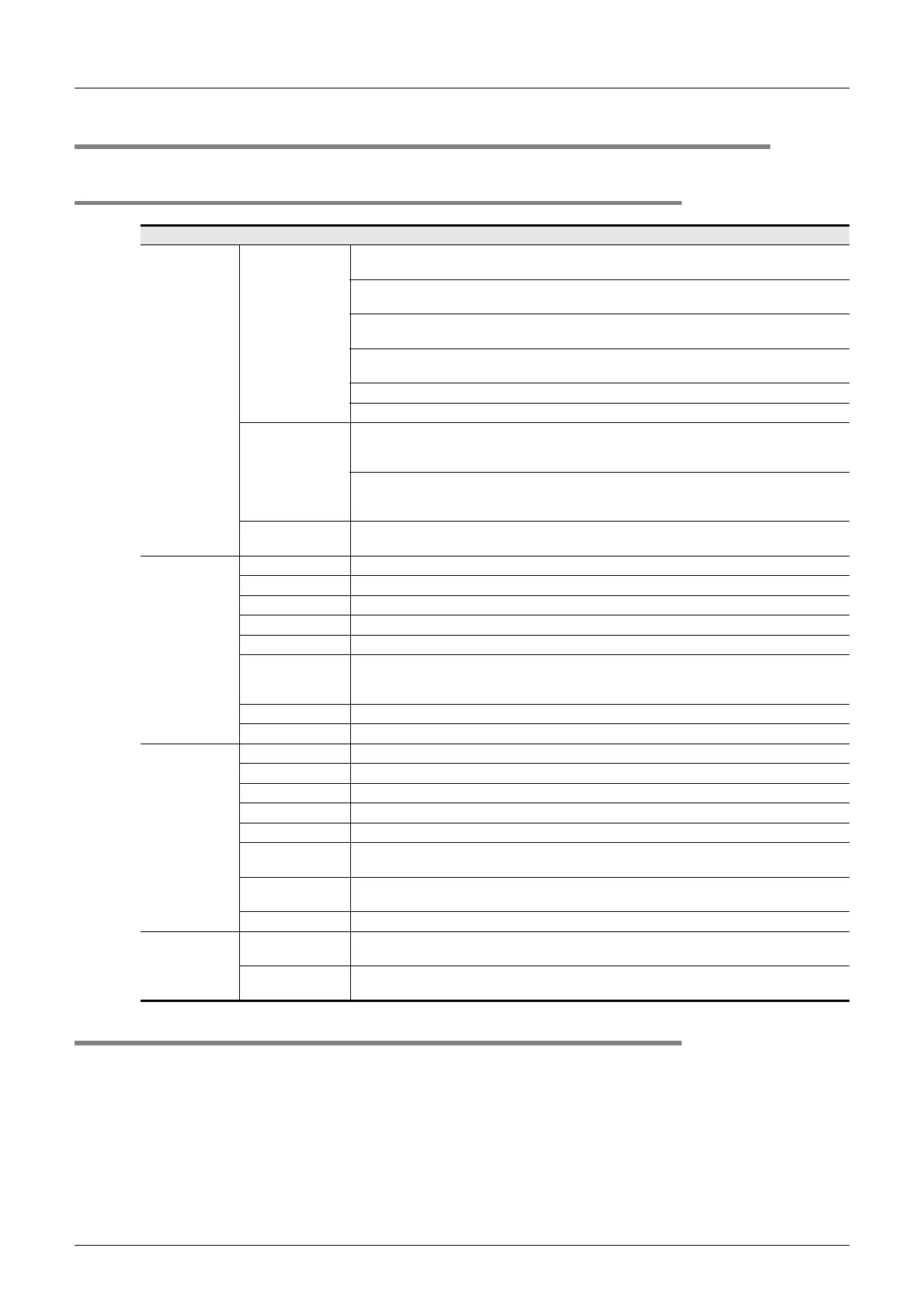
3.4.1 Input specifications
3.4.2 Internal input circuit
For the internal input circuit diagram, refer to the following.
→ For the internal input circuit diagram, refer to Section 5.3
Item Specification
Input signal name
Group 1
X axis interrupt input: X-INT0, X-INT1
Used for interrupt operation
Y axis interrupt input: Y-INT0, Y-INT1
Used for interrupt operation
X axis near-point DOG input: X-DOG
Used for zero return
Y axis near-point DOG input: Y-DOG
Used for zero return
START command for X axis positioning operation: X-START
START command for Y axis positioning operation: Y-START
Group 2
Manual pulse generator input for X axis:
X- φ A+/X- φ A-, X- φ B+/X- φ B-
1 edge count at 2-phase 2-count
Manual pulse generator input for Y axis:
Y- φ A+/Y- φ A-, Y- φ B+/Y- φ B-
1 edge count at 2-phase 2-count
Group 3
External power supply for signals: S/S
Connected to power supply for INT0, INT1, DOG and START
Group 1
Operation display LED ON at input ON
Signal voltage 24V DC +20% -15% (Power is supplied from S/S terminal)
Input current 7.0mA ± 1mA /24V DC
ON current 4.5mA or more
OFF current 1.5mA or less
Signal form
No-voltage contact input
Sink input: NPN open collector transistor
Source input: PNP open collector transistor
Response time Hardware filter 1ms or less
Circuit insulation Photo-coupler insulation
Group 2
Operation display LED ON at input ON
Signal voltage 3 to 5.25V DC
Input current 3.0 to 8.5mA
ON current 3.0mA or more
OFF current 0.5mA or less
Signal form
Differential line driver
(corresponding to AM26LS31)
Response
frequency
2-phases pulse 100KHz or less (Duty 50%)
Circuit insulation Photo-coupler insulation
Group 3
Power supply
voltage
24V DC +20% -15%
Consumption
current
64mA or less

 Loading...


