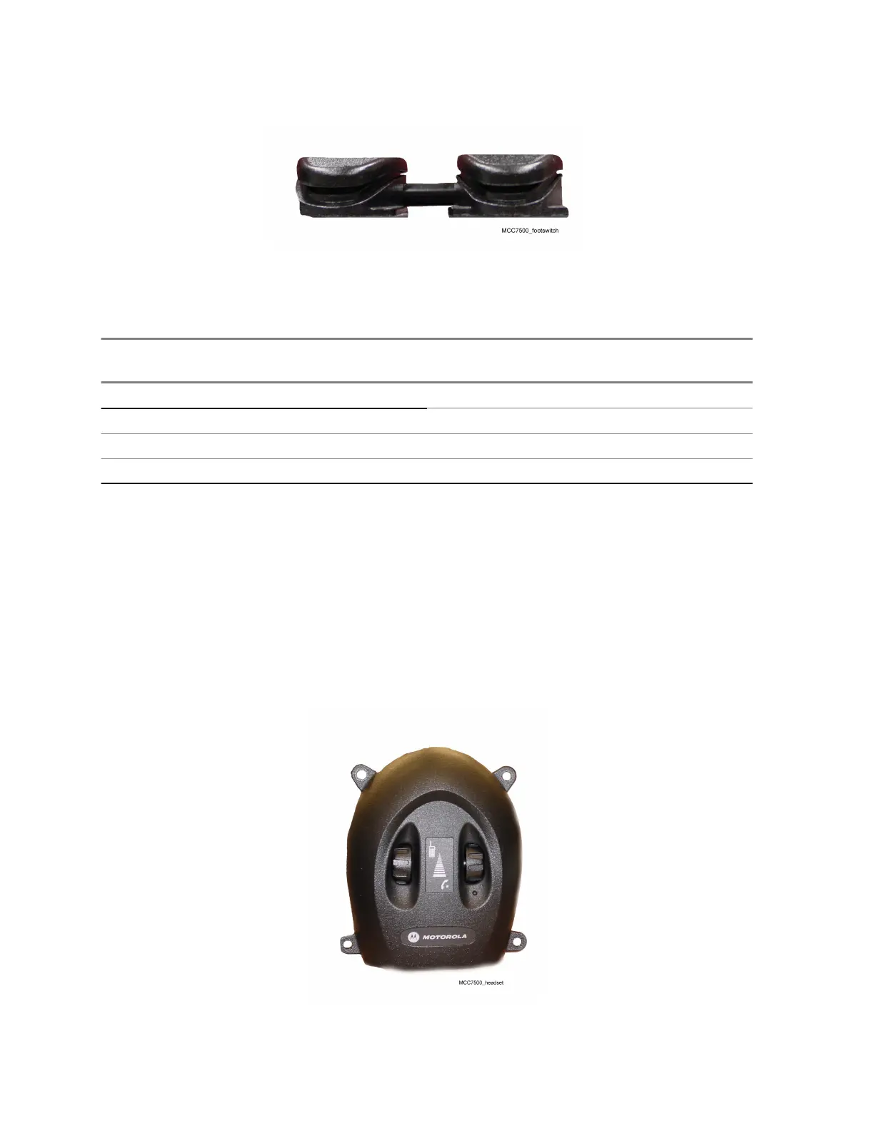
Figure 7: Footswitch
Table 14: Footswitch Pinout
This table presents footswitch connector pinout. The pinout is the same as for Voice Processor Module
(VPM) footswitch port.
Pin Number
Description (+) and (–) symbols indicate pin
polarity
3 PTT In (+)
4
PTT In (–)
5 Monitor In (–)
6 Monitor In (+)
Headset Jacks
The USB Audio Interface Module (USB AIM) can support up to two headset jacks. A headset jack
allows a dispatch console user to use a headset while operating the dispatch console. The headset
jack supports headsets that use either PJ7 (6-wire) or PJ327 (4-wire) long frame connectors. The 6-
wire headsets have a Push-to-Talk (PTT) button while the 4-wire headsets do not have a PTT button.
The headset jacks shipped from the factory are configured for the 6-wire headsets. For the 4-wire
operation, open the housing and make changes, depending on the version of the headset box. For
more information, see Configuring the Headset Jack Box for 4-Wire Operation on page 105.
Figure 8: Headset Jack
The headset jack has two volume controls:
MN000672A01-E
Chapter 4: USB Audio Interface Module
104 Send Feedback
 Loading...