System Integration Module (SIM)
SIM Registers
MC68HC908AB32 — Rev. 1.0 Technical Data
MOTOROLA System Integration Module (SIM) 127
8.8 SIM Registers
The SIM has three memory mapped registers. Table 8-4 shows the
mapping of these registers.
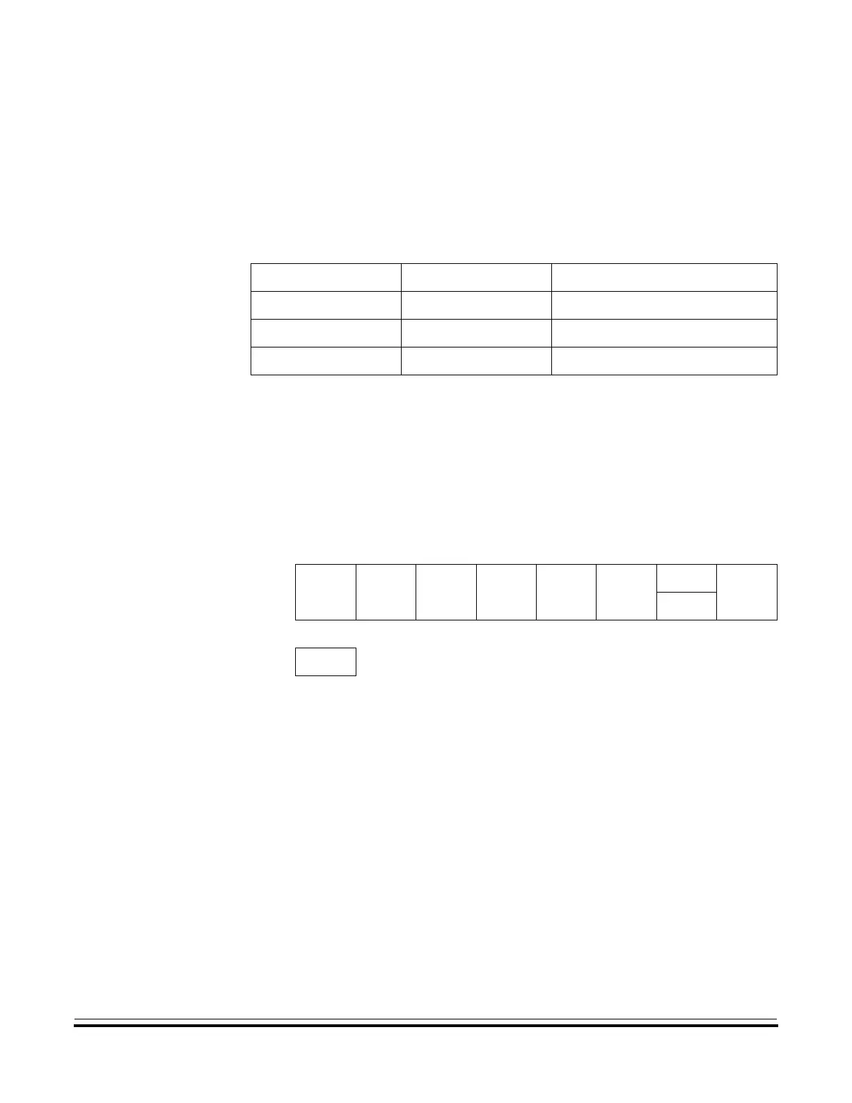
8.8.1 SIM Break Status Register
The SIM break status register (SBSR) contains a flag to indicate that a
break caused an exit from stop or wait mode.
SBSW — SIM Break STOP/WAIT
This status bit is useful in applications requiring a return to stop or wait
mode after exiting from a break interrupt. SBSW can be cleared by
writing a logic 0 to it. Reset clears SBSW.
1 = Stop or wait mode was exited by break interrupt
0 = Stop or wait mode was not exited by break interrupt
SBSW can be read within the break state SWI routine. The user can
modify the return address on the stack by subtracting one from it. The
following code is an example of this.
Table 8-4. SIM Registers
Address Register Access Mode
$FE00 SBSR User
$FE01 SRSR User
$FE03 SBFCR User
Address: $FE00
Bit 7 654321Bit 0
Read:
RRRRRR
SBSW
R
Write: Note
(1)
Reset: 00000000
R = Reserved
Note: 1. Writing a logic 0 clears SBSW.
Figure 8-17. SIM Break Status Register (SBSR)
 Loading...


