7-2 Chapter 7: Troubleshooting
Tones and Status Indicators
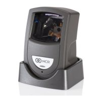
Your 7893 uses tones and LED Status Indicator light to identify problems. It performs
diagnostics that check various scanner functions at different times. Diagnostic checks are made
each time power is applied to the scanner and while the scanner is operating.
If your 7893 does not work properly, you might be able to determine the problem and
correct it without having to send the scanner in for repair. Use the following steps to help
isolate the problem.
1.
Identify exactly what the scanner is doing, or not doing. Pay particular attention to the
LED Status Indicator light and the tone.
2.
Verify that you are operating the scanner according to the procedures described in Chapter
4, Operating Your Scanner.
3.
Refer to the following table to see if your scanner condition is identified. If your specific
problem is not identified, follow your normal repair procedures. This may include sending
your 7893 in for repair.
Error Code Problem Suspect Component
0 No power (LED off) Power supply or PCB assembly
2 RAM test failed PCB assembly
5 Motor too slow Motor
6 Bad non-volatile memory (EEPROM) PCB assembly
9 IBM RS485 – no TERMPWR signal IBM host terminal; cable
11 Laser not turned on PCB assembly
12 Program (ROM sum-check) test failed PCB assembly
13 FPGA failed to program PCB assembly
Scanner State 7893 LED Status Indicator
Idle (Enabled) green, dim, solid
Enabled and in Sleep Mode green, dim, solid
Good Scan or Barcode Still Visible green, bright, solid
Disabled and Awake red, dim, solid
Disabled and in Sleep Mode red, dim, solid
Sleep Mode green, dim, solid
Successful Power On Diagnostics green, dim, solid
Firmware Updating lavender while in firmware flash mode; blinking
lavender while actively flashing an update.
 Loading...
