SECTION 5
DISASSEMBLY AND ASSEMBLY
99
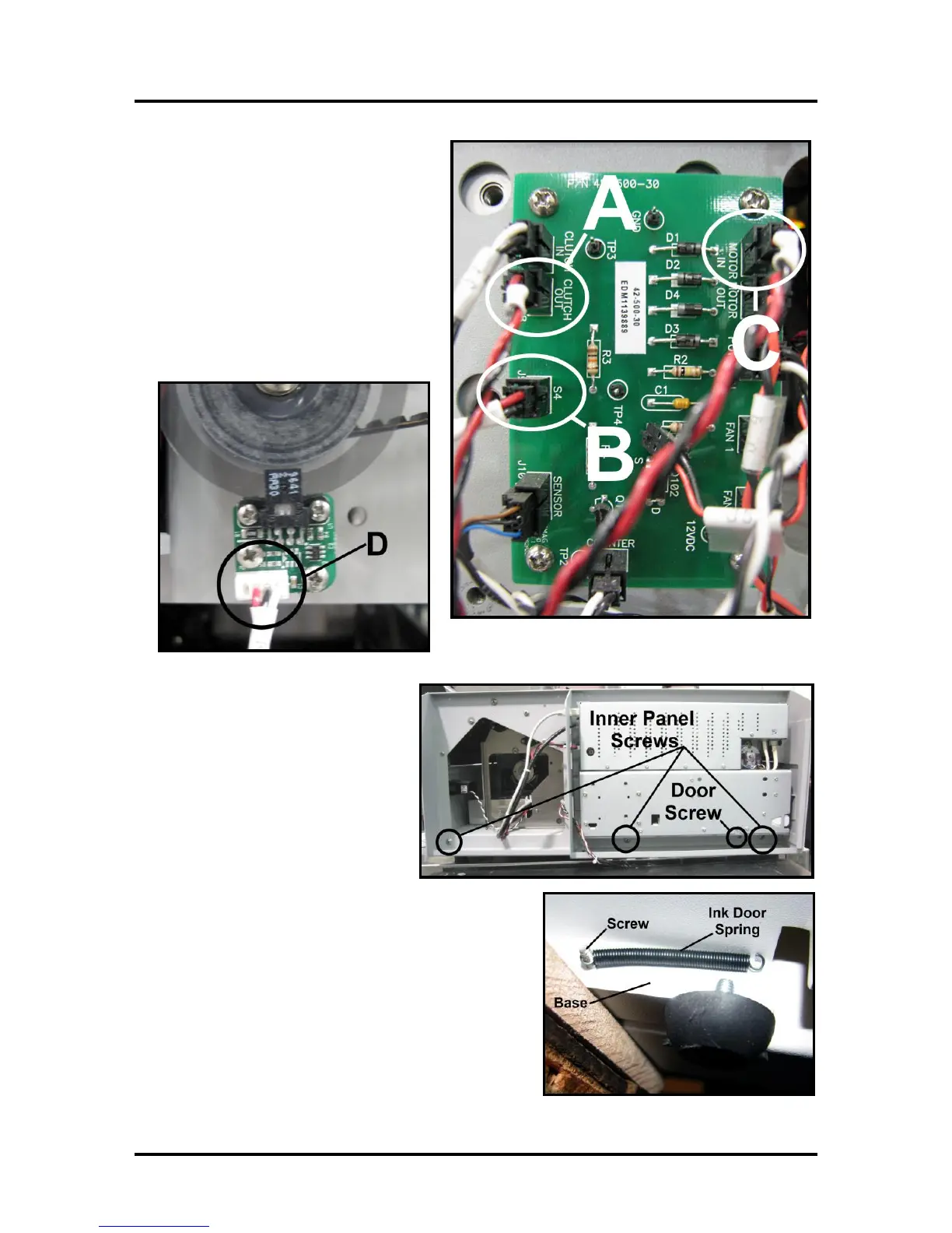
11. Disconnect the following wires from the
Interface Printed Circuit Board located on
the right hand side of the Printer Frame.:
[A] Clutch Out (J8),
[B] S4 (J9)
[C] Motor In (J2).
NOTE: Connector location [C] on Rev B
boards is different than shown here.
[D] Disconnect the Encoder wire from the
Encoder Printed Circuit Board. Pull these
wires clear from the other wiring so they
won't snag when the Print Engine is
removed.
12. Remove Left-hand Inner Side
(operator side) Frame (3 screws).
Remove the Ink Tank Door Spring
mounting screw. First remove the
Door Spring attached to the screw
under the Base Plate. Then remove
the screw. Then carefully remove the
Inner Side Frame from around the
Print Engine and Ink Lines. NOTE:
be careful not to lose the Ink Door
Spring.

 Loading...

