SECTION 5
DISASSEMBLY AND ASSEMBLY
77
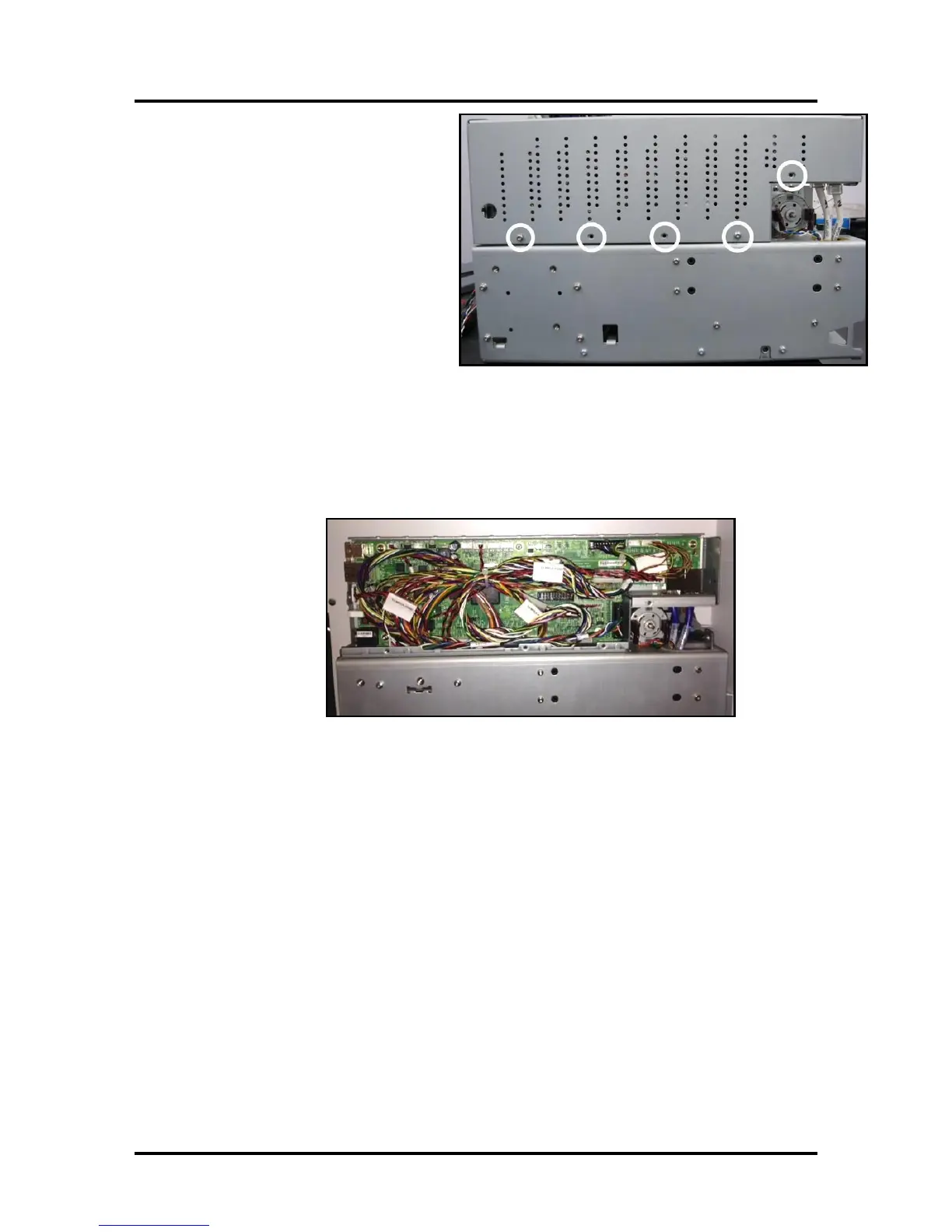
7. Remove the Main PCB Cover
Using a T10 Torx driver remove
the screws that secure the cover.
There will be 4 or 5 screws,
depending on print-engine
version.
Tip: The top section of this
cover wraps around the back-
side of the enclosure. Once the
screws are removed, lift the
cover up and then towards you;
so the cover clears the back side
of the enclosure.
8. Carefully disconnect all connections from Main PCB
IMPORTANT! Do not pull on wires to disconnect; pull on connector. Before
you disconnect; check to be sure each connection is tagged so you know where to
re-attach it.
9. Remove the T10 screws that secure the Main PCB to the frame.
10. Carefully remove the Main PCB.

 Loading...

