SECTION 5
DISASSEMBLY AND ASSEMBLY
78
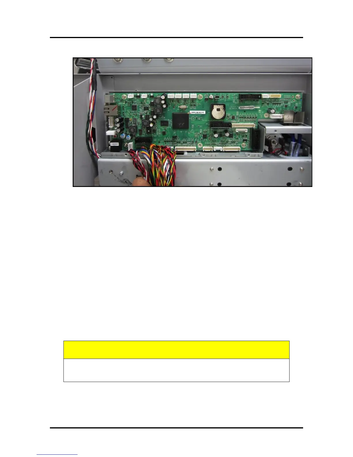
11. Install the New Main PCB to the frame using the T10 screws.
12. Carefully reconnect all connections to the New Main PCB, in the following
order.
Please follow this process, step by step, to be sure each connection is installed
into the appropriate socket.
WARNING: The images shown in the following process are valid for the
installation of a board into a Z3 or higher print-engine. If you have a Z2i engine;
do NOT use the following images to guide you through the connection process.
The cables and socket (connection) positions are different on Z2i boards. We have
not developed a document with Z2i images. If you have a Z2i board installation
you will need to carefully read the tags on the cables and locate the corresponding
socket location on the board (they are labeled).
Tip: Triple check that all connections have been properly made before installing
the Main PCB Cover.
ALWAYS WEAR A WRIST STRAP THAT IS GROUNDED WHEN
TOUCHING ELECTRONIC DEVICES.

 Loading...

