Home
Neopost
Printer
MACH 5
Neopost MACH 5 User Manual
5
of 1
of 1 rating
204 pages
Give review
Manual
Specs
To Next Page
To Next Page
To Previous Page
To Previous Page
Loading...
SECTION 5
DISASSEMBLY AND ASSEMBLY
93
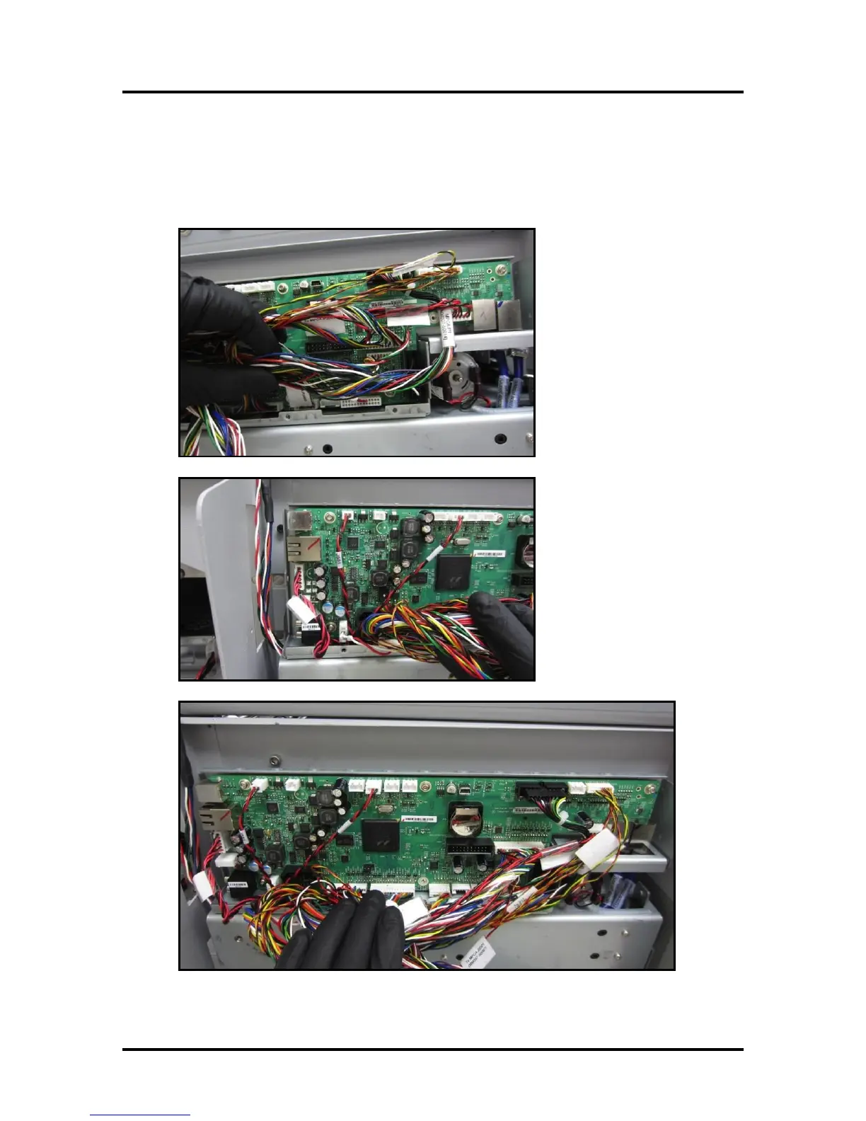
13.
Verify that All Cables Are Ins
talled
NOT
E: There will be 10
open sockets after all cables hav
e been installed.
Open Sockets: J550
, J554, J553, J750, J706, J504, J3
53, J400, J37, P900.
94
96
Table of Contents
Default Chapter
1
Service Guide
1
Safety Precautions
2
Table of Contents
3
SECTION 1 - before You Begin
7
Recommended Troubleshooting Supplies
7
Common Service Tools Needed
7
Minimum Computer System Requirements
8
Print Engine Reference Note
8
If You Have Setup-Operations Questions
8
SECTION 2 - Troubleshooting
9
Print Quality Issues
9
Examples of Print Quality Issues (Including Possible Causes and Solutions)
10
Scuff Marks and Smudging Issues
13
Fuzzy/Distorted Print
15
The Ink Tank(S)
16
The Printhead Cartridge
17
The Printer
19
Dots or Lines Printed on Media
19
Power (Power-Up) Problems
20
Service Station Problems
21
Interface Communication Problems
23
Feeding Problems
24
Error's and Warnings
26
Alert Window Messages
26
Toolbox System Status Messages
27
Air in Ink Lines
33
Ink Accumulating in the Wrong Areas of the Printer
34
Jams in the Printer
35
Removing Jammed Media
35
How to Zero the Tilt Sensor
36
SECTION 3 - Toolbox Service Features
37
Using / Opening the Printer Toolbox
37
Firmware Download Feature
38
Diagnostics Menu
38
System Settings
40
Service Menus
41
Printer Maintenance Configuration Screen
42
Printer Control Configuration Screen
43
Scan Sensors Screen
44
Commands Help Screen
45
Exit Service Menus
45
SECTION 4 - Measurements and Adjustments
46
Drive Belt Tension Adjustment
46
Power Supply
47
Media Sensors
48
Feed Sensor
48
Print Engine Sensors
50
Feeder Encoder Sensor and Encoder Wheel
51
Dust Exhaust Fans
52
Feeder Motor (Feed Section)
52
Clutch (Feed Roller Drive)
53
Feed Roller Drive Pulley Test
54
Print Engine Clamshell (Door) Switch
54
Dual Pinch Valve Connection
55
Print Engine Drive Belt Tension Adjustment
57
Interface (I/O) Board Test Points
59
Section 5 - Disassembly/Assembly Procedures
60
Preparing the Printer for Service
60
Installation and Service Videos (Where to Find)
61
Basic Disassembly
61
Service Disassembly Procedures
61
Left-Hand (Operator) Side Covers
62
Right-Hand (Non-Operator) Side Cover
63
Replacing Digital Counter
64
Replacing Motor Drive Belt or Motor
67
Replacing the Clutch
67
Replacing the Feeder Encoder And/Or Encoder Sensor
68
Replacing Feed Rollers
69
Replacing Delivery Rollers
72
Replacing Interface (I/O) Board
76
Replacing the Main PC Board (MPCA)
77
MPCA (Main Printed Circuit Assembly) Connections
97
Removing the Print Engine
98
Print Engine Basic Disassembly
103
Removing the Print Engine Base
103
Replacing Peristaltic Pump Assembly
104
Replacing Dual Pinch Valve Assembly
104
Cleaning Dual Pinch Valve Sensors
105
Replacing Dual Pinch Valve Sensor PC Board
106
Replacing DPCA Board
109
Replacing Buffer Boxes (3 Per Machine)
110
Replacing the Ink Tank Interface Boards
110
Removing the Pen Driver Printed Circuit Assembly (PCA)
111
Removing the Starwheel Assemblies
111
Replacing the Ink Tank Latches
112
Replacing the Printhead Lever Latch
112
Replacing the Printhead Lever Latch Solenoid
115
Replacing the Clamshell Latch Pins
117
Upper Clamshell Latch Pin Replacement - Kit
117
Lower Clamshell Latch Pin Replacement Kit
122
Replacing the Ink Revolvers
125
Replacing Lifter Motor Assembly or Lifter Gear
127
Replacing Stepper Motor
128
Accessing Items Behind the Main Printed Circuit Assembly (MPCA)
129
Replacing Encoder or Encoder Sensor
130
Replacing Service Station Lifter Arm Sensor
130
Replacing Paper Path Motor or Drive Belt
131
Replacing Belt Drive Gear Pulleys
132
Reinstall the Main Printed Circuit Assembly
133
Accessing Items under the Clamshell Assembly
134
Replacing Paperpath Exit Sensor
134
Replacing Paperpath Entry Sensor
135
Replacing Service Station Sled Printed Circuit Boards
136
Replacing Wiper Motor Flex Cable PCA
136
Replacing Service Station Lifting Arms
137
Section 6 - Service Maintenance
145
Maintenance Schedule
145
Replacing the Ink Tanks
146
Cleaning Ink Tank Contacts
147
Cleaning the Printhead Cartridge
149
Replacing the Printhead Cartridge
150
Printhead Storage & Shelf Life
151
Printhead Service Life
151
Printhead Disposal
151
Cleaning Pen Driver Printed Circuit Board Contacts
152
Inspecting & Cleaning the Lip of the Capping Station
153
Inspecting the Wiper Roller
154
Cleaning/Replacing Service Station Items
155
Removing the Service Station
155
Cleaning the Service Station
158
Wiper Roller Removal and Cleaning or Replacement
158
Wiper Motor Assembly Removal and Cleaning
159
Printing Platen and Capping Station Removal and Cleaning
160
Cleaning the Service Station Tray
160
Suggestion for High Volume Users
160
Installing the Service Station
161
Still Experiencing Print Quality Issues
164
Inspecting/Replacing the Waste Ink Tray
165
Replacing the Sheet Separators
166
Cleaning the Printer Body
167
Cleaning the Feed Rollers and Forwarding Rollers
167
Cleaning the Feed Sensor
168
Cleaning the Ink Revolver Couplings
169
Cleaning the Encoder Wheel - Z2I Engine
169
Cleaning the Lift Arm Sensor
170
Cleaning the Encoder Wheel on the Lift Motor
171
Cleaning Other Items Inside the Print Engine
172
Grit Rollers (Media Transport Rollers)
172
Media (Paperpath) Sensors
172
Paperpath Surfaces
172
Printing Platen Surface
172
Preparing Printer for Transport
174
Local Relocation
174
Remote Relocation or Shipping
174
Lubricating the Service Station Friction Points
176
Lubricating the Grit Roller Ground Clips/Springs
180
Reinstalling or Replacing the Service Station
181
Appendix Section
185
Appendix A -Specifications
185
Appendix B - Supplies and Optional Hardware
186
Appendix C - Service Station Guide Installation Instructions
187
Remove the Service Station
188
Appendix D - Ink Delivery System (IDS)
194
Theory of Operation
194
Appendix E - Z2I Wiring Diagram
196
Appendix F - Z3/Z4/MR Wiring Diagram
197
Appendix G -Interface (I/O) Board (42-500-30) Schematic
198
Appendix H -Interface (I/O) Board (42-500-30 Rev B) Schematic
199
Appendix I -Side Frame Modification
200
Index
201
5
Based on 1 rating
Ask a question
Give review
Questions and Answers:
Need help?
Do you have a question about the Neopost MACH 5 and is the answer not in the manual?
Ask a question
Neopost MACH 5 Specifications
General
Brand
Neopost
Model
MACH 5
Category
Printer
Language
English
Related product manuals
Neopost AS-970C
128 pages
Neopost AS-710
167 pages
Neopost DS-600i
58 pages