Safety
information
Product
information
Mechanical
installation
Electrical
installation
Getting
started
Basic
parameters
Running
the motor
Optimization
NV Media Card
Operation
Building
Automation
Advanced
parameters
Technical
data
Diagnostics
UL listing
information
132 HVAC Drive H300
Issue Number: 3
• A stationary autotune can be used when the motor is loaded and it is
not possible to remove the load from the motor shaft. The stationary
autotune measures the Stator Resistance (05.017) and Transient
Inductance (05.024) of the motor. These are used to calculate the
current loop gains, and at the end of the test the values in Pr 04.013
and Pr 04.014 are updated. A stationary autotune does not measure
the power factor of the motor so the value on the motor nameplate
must be entered into Pr 05.010.
To perform a Stationary autotune, set Pr 00.024 to 1, and provide the
drive with both an enable signal (on terminal 29) and a run signal (on
terminal 24).
Autotune test 2:
• A rotating autotune should only be used if the motor is unloaded. A
rotating autotune first performs a stationary autotune, a rotating test
is then performed which the motor is accelerated with currently
selected ramps up to a frequency of Rated Frequency (05.006)
x
2
/
3
, and the frequency is maintained at the level for up to 40 s.
During the rotating autotune the Stator Inductance (05.025) is
modified by the drive. The power factor is also modified for user
information only, but is not used after this point as the stator
inductance is used in the vector control algorithm instead. To
perform a Rotating autotune, set Pr 00.024 to 2, and provide the
drive with both an enable signal (on terminal 29) and a run signal (on
terminal 24).
Following the completion of an autotune test, the drive will go into the
inhibit state. The drive must be placed into a controlled disable condition
before the drive can be made to run at the required reference. The drive
can be put in to a controlled disable condition by removing the Safe
Torque Off signal from terminal 29, setting the Drive Enable (06.015) to
OFF (0) or disabling the drive via the control word (Pr 06.042 &
Pr 06.043).
RFC-S
There are three autotune tests available in RFC-S sensorless mode, a
stationary autotune and a rotating autotune.
Autotune test 1:
• The stationary autotune can be used to measure all the necessary
parameters for basic control. The tests measure Stator Resistance
(05.017), Ld (05.024) and No Load Lq (05.072) The Stator
Resistance (05.017) and the Ld (05.024) are then used to set up
Current controller Kp Gain (04.013) and Current Controller Ki Gain
(04.014). To perform a Stationary autotune, set Pr 00.024 to 1, and
provide the drive with both an enable signal (on terminal 29) and a
run signal (on terminal 24).
Autotune test 2:
• In sensorless mode, if Rotating autotune is selected (Pr 00.024 = 2),
then a stationary autotune is performed.
Autotune test 6:
• Locket rotor test for load dependant parameters. This test is not
impemented at the time of writing.
Following the completion of an autotune test the drive will go into the
inhibit state. The drive must be placed into a controlled disable condition
before the drive can be made to run at the required reference. The drive
can be put in to a controlled disable condition by removing the Safe
Torque Off signal from terminal 29, setting the drive Enable Parameter
(06.015) to OFF (0) or disabling the drive via the control word (Pr 06.042
& Pr 06.043).
In modes 2 and 3, a current loop loss trip is generated if the current falls
below 3 mA.
In modes -4, -3, 2 and 3 the analog input level goes to 0.0 % if the input
current falls below 3 mA.
In modes -2 and -1 the analog input remains at the value it had in the
previous sample before the current fell below 3 mA.
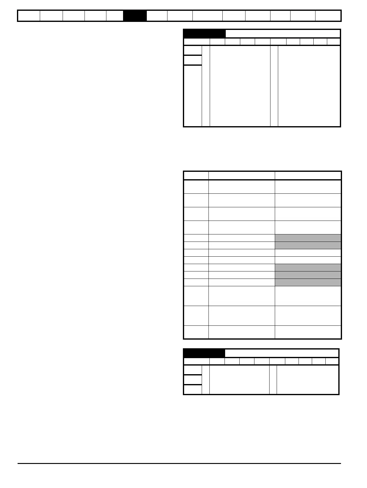
Pr 00.026 sets the destination of analog input 1
00.025 {07.707} Analog Input 1 Mode
RW Txt US
OL
Ú
4-20 mA Low (-4),
20-4 mA Low (-3),
4-20 mA Hold (-2),
20-4 mA Hold (-1),
0-20 mA (0),
20-0 mA (1),
4-20 mA Trip (2),
20-4 mA Trip (3),
4-20 mA (4),
20-4 mA (5), Volt (6),
Therm Short Cct (7),
Thermistor (8),
Therm No Trip (9)
Ö
4-20 mA (4)
RFC-A
RFC-S
Pr Value Pr string Comments
-4 4-20 mA Low
4-20 mA low value on
current loss (1)
-3 20-4 mA Low
20-4 mA low value on
current loss (1)
-2 4-20 mA Hold
4-20 mA hold at level before
loss on current loss
-1 20-4 mA Hold
20-4 mA hold at level before
loss on current loss
0 0-20 mA
1 20-0 mA
2 4-20 mA Trip 4-20 mA trip on current loss
3 20-4 mA Trip 20-4 mA trip on current loss
4 4-20 mA
5 20-4 mA
6Volt
7 Therm Short Cct
Temperature Measurement
Input With Short Circuit
Detection
8 Thermistor
Temperature Measurement
Without Short Circuit
Detection
9 Therm No Trip
Temperature Measurement
Input With No Trips
00.026 {07.010} Analog Input 1 Destination
RW Num DE PT US
OL
Ú
00.000 to 59.999
Ö
01.036RFC-A
RFC-S