Safety
information
Product
information
Mechanical
installation
Electrical
installation
Getting
started
Basic
parameters
Running the
motor
Optimization
NV Media Card
Operation
Building
Automation
Advanced
parameters
Technical
data
Diagnostics
UL listing
information
84 HVAC Drive H300
Issue Number: 3
Figure 4-13 Input line reactor dimensions
4.2.4 Input inductor calculation
To calculate the inductance required (at Y%), use the following equation:
Where:
I = drive rated input current (A)
L = inductance (H)
f = supply frequency (Hz)
V = voltage between lines
4.3 Supplying the drive with DC
All drive sizes have the option to be powered from an external DC power supply. Refer to section 3.12 Electrical terminals on page 64 to identify the
location of DC supply connections.
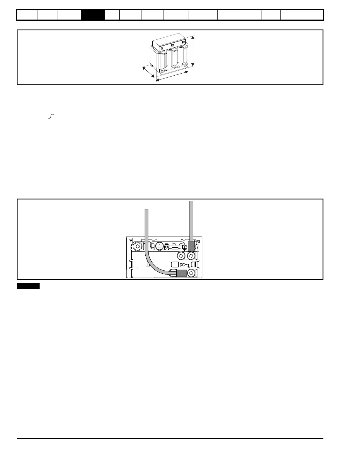
The DC supply connections for size 3 and 4 are located under the DC / Terminal cover. Figure 4-14 below shows DC supply connections and cable
routing.
Figure 4-14 DC supply connections (size 3 shown)
The Internal EMC filter and plastics have been removed from the above Figure 4-14 to demonstrate the routing of the DC cables.
L
Y
100
----------
V
3
-------
×
1
2πfI
------------
×=