Safety
information
Product
information
Mechanical
installation
Electrical
installation
Getting
started
Basic
parameters
Running the
motor
Optimization
NV Media Card
Operation
Building
Automation
Advanced
parameters
Technical
data
Diagnostics
UL listing
information
HVAC Drive H300 163
Issue Number: 3
8.4.5 Fire mode
Emergency ventilation or fire mode allows for the purging of air from a
structure during a fire. It is enabled if Pr 1.053 is set to a non zero value
and activated when Pr 1.054 is set to one. When activated, the pre-ramp
reference (Pr 1.003) is set to the value of Pr 1.053 and the normal drive
controls are overridden as follows:
1. Drive enable is only controlled by the Enable input (Pr 6.015). The
control word (Pr 6.043) cannot be used to disable the drive.
2. The internal run command is forced to be active. The normal drive
sequencing bits (Pr 6.030 to Pr 6.034) and the control word have no
effect.
3. The limit switch functions (Pr 6.035 and Pr 6.036) have no effect and
will not stop the motor.
4. The hard speed reference is forced to zero. The hard speed
reference should not be used when fire mode is likely to be activated
as this will cause an abrupt change of speed.
5. The hand/off/auto function is disabled. If this system is in the hand
state when fire mode is activated it will be forced to the off state, so
that hand state is not active when fire mode is de-activated.
6. Keypad mode is disabled.
7. All latching mode states are reset.
When Pr 1.054 is subsequently set to zero the drive returns to normal
operation.
Pr 1.054 can only be changed from a digital input and the default
configuration allocates this to digital input 4.
If fire mode is activated when the drive is in a tripped state then the trip is
reset.
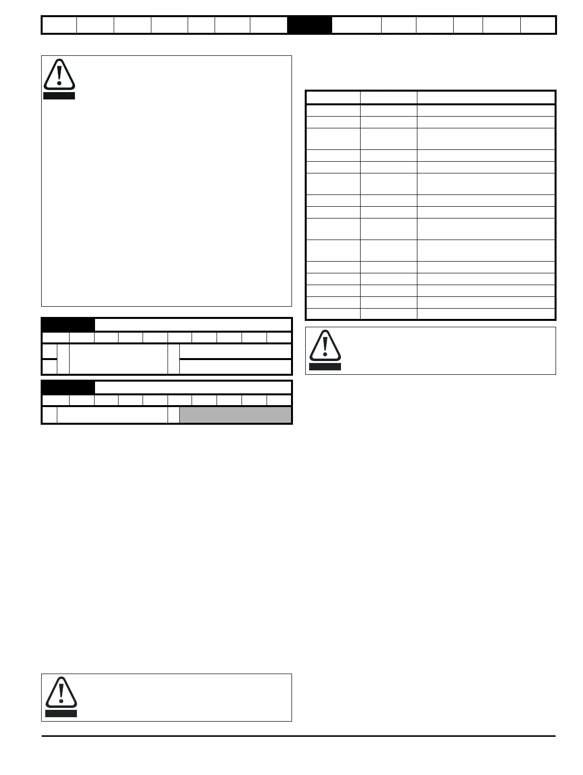
Only the trips listed in the following table can be initiated while fire mode
is active.
8.4.6 Advanced process PID
The Advanced Process PID comprises two PID controllers. PID 1 can be
configured to operate as follows (refer to Pr 14.059 for details).
• Single setpoint and single feedback
• Single setpoint and dual feedback
• Dual setpoints and dual feedback
PID 2 always operates as a single setpoint, single feedback controller.
When a feedback signal requires square root conversion (e.g. airflow),
square root scaling can be applied to PID 1 feedback (see Pr 14.058,
Pr 14.060, Pr 14.061 and Pr 14.062). PID 1 also includes a pre-sleep
boost level facility (see Pr 14.028 and Pr 14.029) to reduce frequent
transitions into sleep mode when the PID is used.
The PID system is always active even when the output destination
parameters are not set to a valid destination parameter. This allows the
PID controllers to be used independently from the drive via a building
automation network.
Fire Mode - Important Warning.
When Fire Mode is active the motor overload and thermal
protection are disabled, as well as a number of drive
protection functions. Fire Mode is provided for use only in
emergency situations where the safety risk from disabling
protection is less than the risk from the drive tripping -
typically in smoke extraction operation to permit evacuation
of a building. The use of Fire Mode itself causes a risk of fire
from overloading of the motor or drive, so it must only be
used after careful consideration of the balance of risks.
Care must be taken to prevent inadvertent activation or de-
activation of Fire Mode. Fire Mode is indicated by a flashing
display text warning "Fire mode active".
Care must be taken to ensure that parameters Pr 1.053 or
Pr 1.054 are not inadvertently re-allocated to different inputs
or variables. It should be noted that, by default, Pr 1.054 is
controlled from digital input 4 and changing Pr 8.024 can re-
allocate this digital input to another parameter. These
parameters are at access level 2 in order to minimize the risk
of inadvertent or unauthorized changes. It is recommended
that User Security be applied to further reduce the risk (see
section 5.9 Parameter access level and security on
page 117). These parameters may also be changed via serial
communications so adequate precautions should be taken if
this functionality is utilized.
1.053 Fire mode reference
RW Uni US
OL
Ú
SPEED_FREQ_MAX
Hz/rpm
Ö
0.0 Hz
RFC
0.0 rpm
1.054 Fire mode activation
RO Bit NC US
Ú
OFF (0) or On (1)
Ö
Care should be taken when modifying parameters as setting
Pr 1.053 to zero inhibits the fire mode function and changing
Pr 8.024 (Digital Input 4 source) could result in digital input 4
source to be allocated to a parameter other than Pr 1.054.
Trip number String Cause of trip
2 Over Volts DC bus over-voltage
3 OI ac AC instantaneous over-current
4 OI brake
Braking resistor instantaneous over
current
5 PSU Drive power supply fault
9 PSU 24V 24 V internal power supply overload
21 OHt inverter
Power device over temperature based
on thermal model
31 EEPROM EEPROM failure
36 User Save User parameter save error
37
Power Down
Save
Power down save parameter error
109 OI dc
Power module over current detected
from on state voltage monitoring
200 Slot1 HF Slot 1 option module failure
205 Slot2 HF Slot 2 option module failure
210 Slot2 HF Slot 3 option module failure
217 to 249 HF17 to HF32 Hardware faults
250 Slot4 HF Slot 4 factory fit option failure
It is possible for the drive or motor to become damaged when
operating in fire mode because some of the drive thermal
protection trips are disabled.