Safety
information
Product
information
Mechanical
installation
Electrical
installation
Getting
started
Basic
parameters
Running the
motor
Optimization
NV Media Card
Operation
Building
Automation
Advanced
parameters
Technical
data
Diagnostics
UL listing
information
HVAC Drive H300 75
Issue Number: 3
4 Electrical installation
Many cable management features have been incorporated into the
product and accessories, this chapter shows how to optimize them. Key
features include:
• Safe Torque Off function
• Internal EMC filter
• EMC compliance with shielding / grounding accessories
• Product rating, fusing and cabling information
4.1 Power connections
4.1.1 AC and DC connections
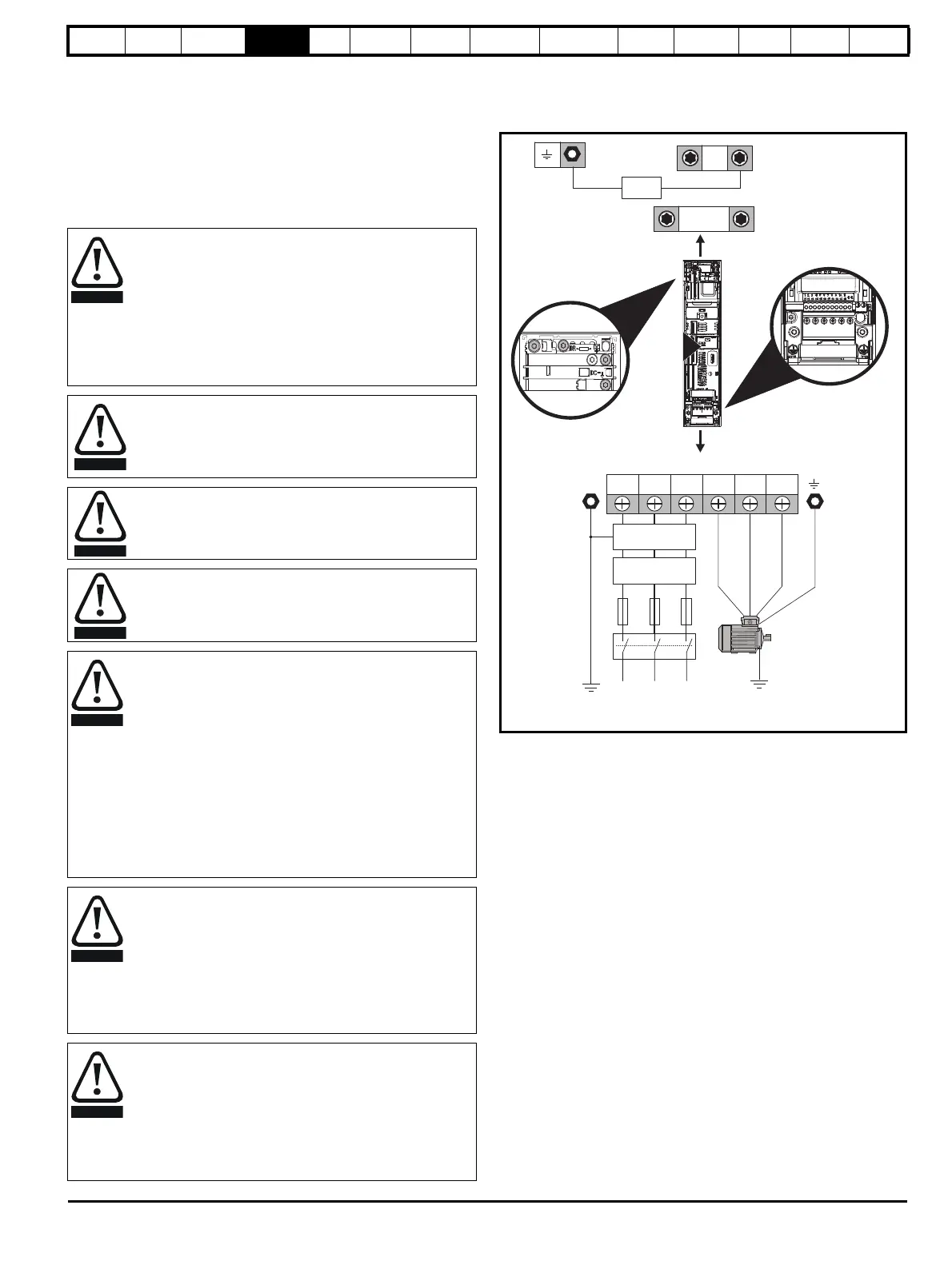
Figure 4-1 Size 3 power connections
See Figure 4-8 for further information on ground connections.
Electric shock risk
The voltages present in the following locations can cause
severe electric shock and may be lethal:
• AC supply cables and connections
• DC cables and connections
• Output cables and connections
• Many internal parts of the drive, and external option units
Unless otherwise indicated, control terminals are single
insulated and must not be touched.
Isolation device
The AC and / or DC power supply must be disconnected
from the drive using an approved isolation device before any
cover is removed from the drive or before any servicing work
is performed.
STOP function
The STOP function does not remove dangerous voltages
from the drive, the motor or any external option units.
Safe Torque Off function
The Safe Torque Off function does not remove dangerous
voltages from the drive, the motor or any external option
units.
Stored charge
The drive contains capacitors that remain charged to a
potentially lethal voltage after the AC and / or DC power
supply has been disconnected. If the drive has been
energized, the AC and / or DC power supply must be
isolated at least ten minutes before work may continue.
Normally, the capacitors are discharged by an internal
resistor. Under certain, unusual fault conditions, it is possible
that the capacitors may fail to discharge, or be prevented
from being discharged by a voltage applied to the output
terminals. If the drive has failed in a manner that causes the
display to go blank immediately, it is possible the capacitors
will not be discharged. In this case, consult Control
Techniques or their authorized distributor.
Equipment supplied by plug and socket
Special attention must be given if the drive is installed in
equipment which is connected to the AC supply by a plug
and socket. The AC supply terminals of the drive are
connected to the internal capacitors through rectifier diodes
which are not intended to give safety isolation. If the plug
terminals can be touched when the plug is disconnected
from the socket, a means of automatically isolating the plug
from the drive must be used (e.g. a latching relay).
Permanent magnet motors
Permanent magnet motors generate electrical power if they
are rotated, even when the supply to the drive is
disconnected. If that happens then the drive will become
energized through its motor terminals.
If the motor load is capable of rotating the motor when the
supply is disconnected, then the motor must be isolated from
the drive before gaining access to any live parts.
L1 L2
L2L1 L3 U V W
Optional EMC
filter
Optional
line reactor
Fuses
L3
Mains
Supply
Motor
Optional ground
connection
Supply
Ground
PE
AC Connections
+DC
-DC
Internal
EMC filter
3