Safety
information
Product
information
Mechanical
installation
Electrical
installation
Getting
started
Basic
parameters
Running the
motor
Optimization
NV Media Card
Operation
Building
Automation
Advanced
parameters
Technical
data
Diagnostics
UL listing
information
HVAC Drive H300 161
Issue Number: 3
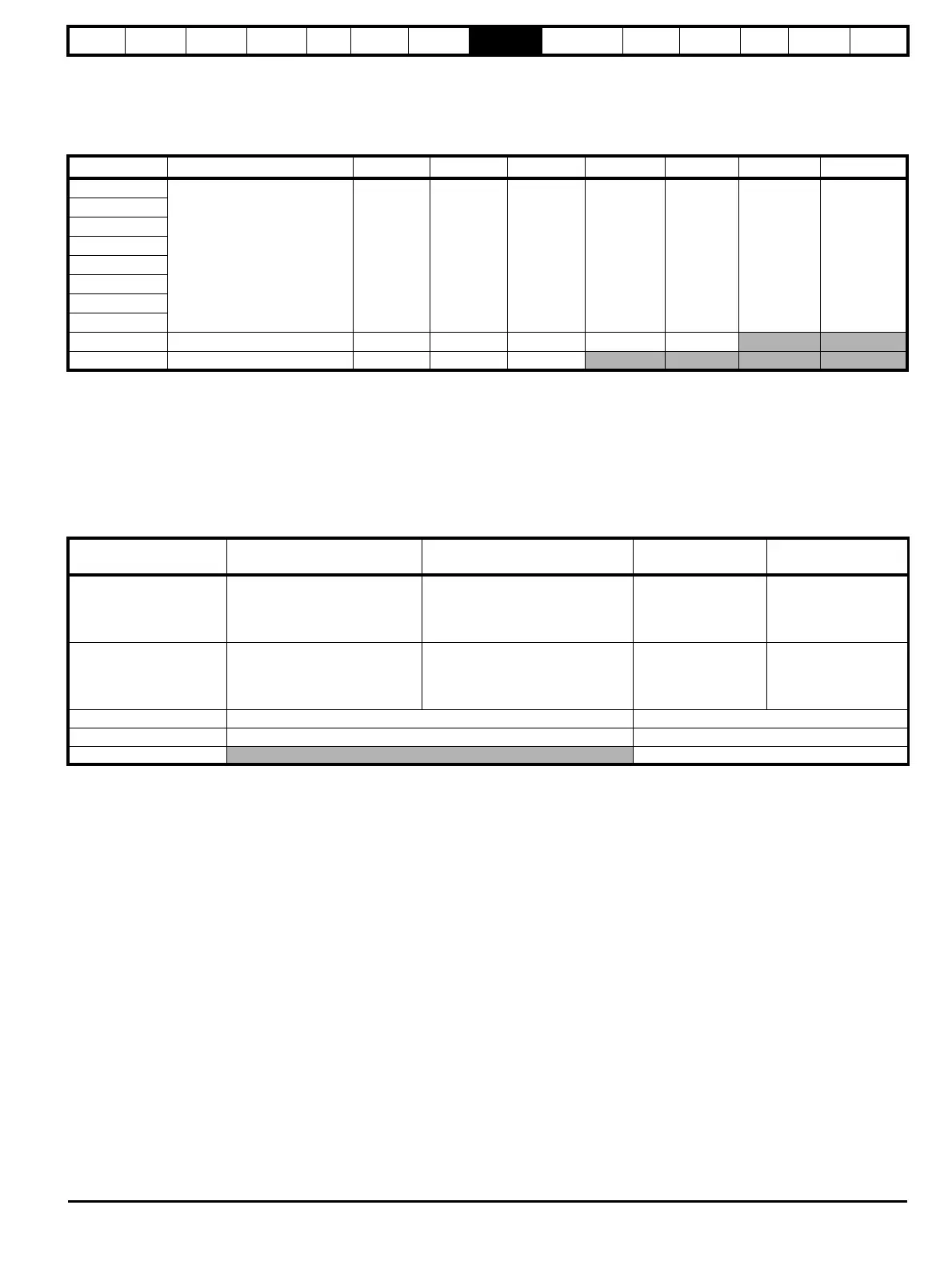
8.3 Switching frequency
The default switching frequency is 3 kHz, however this can be increased up to a maximum of 16 kHz by Pr 05.018 (dependent on drive size). The
available switching frequencies are shown below.
Table 8-1 Available switching frequencies
If the switching frequency is increased from 3 kHz the following apply:
1. Increased heat loss in the drive, which means that derating to the output current must be applied.
See the derating tables for switching frequency and ambient temperature in section 12.1.1 Power and current ratings (Derating for switching
frequency and temperature) on page 259.
2. Reduced heating of the motor - due to improved output waveform quality.
3. Reduced acoustic noise generated by the motor.
4. Increased sample rate on the speed and current controllers. A trade off must be made between motor heating, drive heating and the demands of
the application with respect to the sample time required.
Table 8-2 Sample rates for various control tasks at each switching frequency
Drive size Model 2 kHz 3 kHz 4 kHz 6 kHz 8 kHz 12 kHz 16 kHz
3
All 999999 9
4
5
6
7
8
9
10
11 400 V 99999
11 575 and 690 V 999
3, 6, 12
kHz
2, 4, 8, 16
kHz
Open loop
RFC-A
RFC-S
Level 1
3 kHz = 167μs 6 kHz = 83 μs
12 kHz = 83 μs
2 kHz = 250 μs
4 kHz = 125 μs
8 kHz = 62.5 μs
16 kHz = 62.5 μs
Peak limit Current controllers
Level 2 250 μs
2 kHz -500 μs
4 kHz - 250 μs
8 kHz - 125 μs
16 kHz - 125 μs
Current limit and ramps
Speed controller and
ramps
Level 3 1 ms Voltage controller
Level 4 4 ms Time critical user interface
Background Non-time critical user interface