Safety
information
Product
information
Mechanical
installation
Electrical
installation
Getting
started
Basic
parameters
Running the
motor
Optimization
NV Media Card
Operation
Building
Automation
Advanced
parameters
Technical
data
Diagnostics
UL listing
information
300 HVAC Drive H300
Issue Number: 3
OHt dc bus DC bus over temperature
27
The OHt dc bus trip indicates a DC bus component over temperature based on a software thermal model. The drive
includes a thermal protection system to protect the DC bus components within the drive. This includes the effects of the
output current and DC bus ripple. The estimated temperature is displayed as a percentage of the trip level in Pr 07.035. If
this parameter reaches 100 % then an OHt dc bus trip is initiated. The drive will attempt to stop the motor before tripping. If
the motor does not stop in 10 seconds the drive trips immediately.
It is also possible in a multi-power module system for DC bus over-temperature to be detected from within the power stage.
From this source the estimated temperature as a percentage of trip is not available and the trip is indicated as follows:
Recommended actions:
• Check the AC supply voltage balance and levels
• Check DC bus ripple level
• Reduce duty cycle
• Reduce motor load
• Check the output current stability. If unstable;
Check the motor map settings with motor nameplate (Pr 05.006, Pr 05.007, Pr 05.008, Pr 05.009, Pr 05.010,
Pr 05.011) – (All Modes)
Disable slip compensation (Pr 05.027 = 0) – (Open loop)
Disable dynamic V to F operation (Pr 05.013 = 0) - (Open loop)
Select fixed boost (Pr 05.014 = Fixed) – (Open loop)
Select high stability space vector modulation (Pr 05.020 = 1) – (Open loop)
Disconnect the load and complete a rotating autotune (Pr 05.012) – (RFC-A, RFC-S)
Reduce speed loop gains (Pr 03.010, Pr 03.011, Pr 03.012) – (RFC-A, RFC-S)
Add a speed feedback filter value (Pr 03.042) – (RFC-A, RFC-S)
Add a current demand filter (Pr 04.012) – (RFC-A, RFC-S)
Check encoder signals for noise with an oscilloscope (RFC-A, RFC-S)
Check encoder mechanical coupling - (RFC-A, RFC-S)
OHt Inverter Inverter over temperature based on thermal model
21
This trip indicates that an IGBT junction over-temperature has been detected based on a firmware thermal model. The sub-
trip indicates which model has initiated the trip in the form xxyzz as given below:
Recommended actions with sub-trip 100:
• Reduce the selected drive switching frequency
• Ensure Auto-switching Frequency Change Disable (05.035) is set to Off
• Reduce duty cycle
• Increase acceleration / deceleration rates
• Reduce motor load
• Check DC bus ripple
• Ensure all three input phases are present and balanced
Recommended actions with sub-trip 300:
• Reduce the braking load.
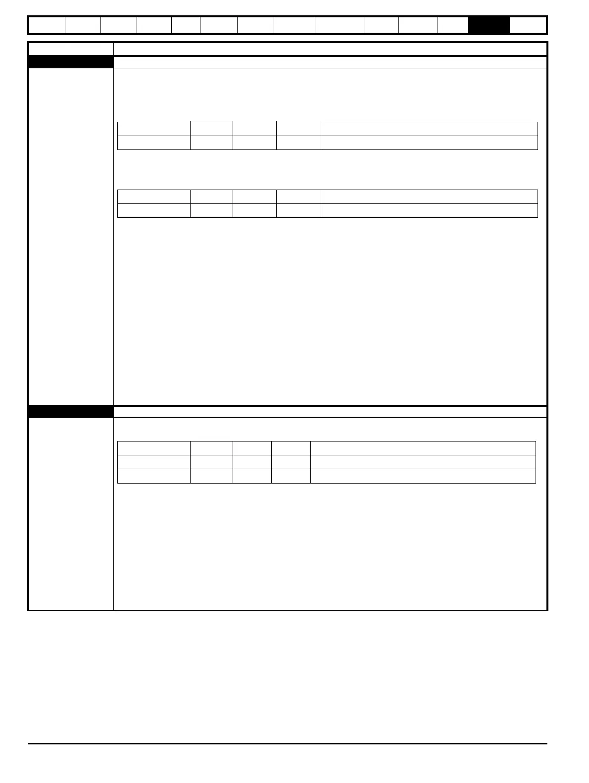
Trip Diagnosis
Source xx y zz Description
Control system 00 2 00 DC bus thermal model gives trip with sub-trip 0
Source xx y zz Description
Control system 01 0 00 Power stage gives trip with sub-trip 0
Source xx y zz Description
Control system 00 1 00 Inverter thermal model
Control system 00 3 00 Braking IGBT thermal model