Safety
information
Product
information
Mechanical
installation
Electrical
installation
Getting
started
Basic
parameters
Running the
motor
Optimization
NV Media Card
Operation
Building
Automation
Advanced
parameters
Technical
data
Diagnostics
UL listing
information
280 HVAC Drive H300
Issue Number: 3
12.1.24 Electromagnetic compatibility (EMC)
This is a summary of the EMC performance of the drive. For full details,
refer to the EMC Data Sheet which can be obtained from the supplier of
the drive.
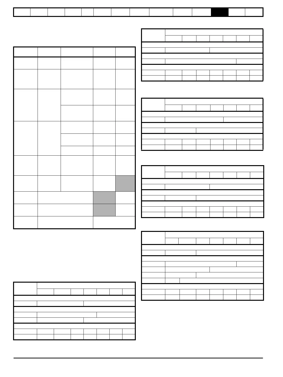
Table 12-30 Immunity compliance
1
See section 4.11.7 Variations in the EMC wiring on page 103 for
control ports for possible requirements regarding grounding and external
surge protection
Emission
The drive contains an in-built filter for basic emission control. An
additional optional external filter provides further reduction of emission.
The requirements of the following standards are met, depending on the
motor cable length and switching frequency.
Table 12-31 Size 3 emission compliance (200 V drives)
Table 12-32 Size 3 emission compliance (400 V drives)
Table 12-33 Size 4 emission compliance (200 V drives)
Table 12-34 Size 4 emission compliance (400 V drives)
Table 12-35 Size 5 emission compliance (200 V drives)
Standard
Type of
immunity
Test specification Application Level
IEC61000-4-2
EN61000-4-2
Electrostatic
discharge
6 kV contact
discharge
8 kV air discharge
Module
enclosure
Level 3
(industrial)
IEC61000-4-3
EN61000-4-3
Radio
frequency
radiated field
10 V/m prior to
modulation
80 - 1000 MHz
80 % AM (1 kHz)
modulation
Module
enclosure
Level 3
(industrial)
IEC61000-4-4
EN61000-4-4
Fast transient
burst
5/50 ns 2 kV
transient at 5 kHz
repetition frequency
via coupling clamp
Control lines
Level 4
(industrial
harsh)
5/50 ns 2 kV
transient at 5 kHz
repetition frequency
by direct injection
Power lines
Level 3
(industrial)
IEC61000-4-5
EN61000-4-5
Surges
Common mode 4 kV
1.2/50 μs waveshape
AC supply
lines:
line to ground
Level 4
Differential mode
2 kV
1.2/50 μs waveshape
AC supply
lines:
line to line
Level 3
Lines to ground
Signal ports to
ground
1
Level 2
IEC61000-4-6
EN61000-4-6
Conducted
radio
frequency
10V prior to
modulation
0.15 - 80 MHz
80 % AM (1 kHz)
modulation
Control and
power lines
Level 3
(industrial)
IEC61000-4-11
EN61000-4-11
Voltage dips
and
interruptions
-30 % 10 ms
+60 % 100 ms
-60 % 1 s
<-95 % 5 s
AC power
ports
IEC61000-6-1
EN61000-6-
1:2007
Generic immunity standard for the
residential, commercial and light -
industrial environment
Complies
IEC61000-6-2
EN61000-6-
2:2005
Generic immunity standard for the
industrial environment
Complies
IEC61800-3
EN61800-
3:2004
Product standard for adjustable
speed power drive systems
(immunity requirements)
Meets immunity
requirements for first and
second environments
Motor cable
length (m)
Switching Frequency (kHz)
234681216
Using internal filter:
0 – 2 C3 C4
Using internal filter and ferrite ring (2 turns):
0 – 10 C3 C4
10-20 C3 C4
Using external filter:
0 – 20 C1 C1 C2 C2 C2 C2 C2
20 – 100 C2 C2 C3C3C3C3C3
Motor cable
length (m)
Switching Frequency (kHz)
2 3 4 6 8 12 16
Using internal filter:
0 – 5 C3 C4
Using internal filter and ferrite ring (2 turns):
0 – 10 C3 C4
Using external filter:
0 – 20 C1 C1 C2 C2 C2 C2 C2
20 – 100 C2 C2 C3 C3 C3 C3 C3
Motor cable
length (m)
Switching Frequency (kHz)
234681216
Using internal filter:
0 – 2 C3 C4
Using internal filter and ferrite ring (2 turns):
0 – 4 C3 C4
Using external filter:
0 – 20 C1 C1 C2 C2 C2 C2 C2
20 – 100 C2 C2 C3 C3 C3 C3 C3
Motor cable
length (m)
Switching Frequency (kHz)
2 3 4 6 8 12 16
Using internal filter:
0 – 4 C3 C4
Using internal filter and ferrite ring (2 turns):
0 – 10 C3 C4
Using external filter:
0 – 20 C1 C1 C2 C2 C2 C2 C2
20 – 100 C2 C2C3C3C3C3C3
Motor cable
length (m)
Switching Frequency (kHz)
2 3 4 6 8 12 16
Using internal filter:
0 – 2 C3 C4
Using internal filter and ferrite ring (1 turn – no advantage to 2 turns):
0 – 2 C3 C4
0 – 5 C3 C4
0 – 7 C3 C4
0 – 10 C3 C4
Using external filter:
0 – 20 C1 C1 C2 C2 C2 C2 C2
20 – 100 C2 C2 C3 C3 C3 C3 C3