Safety
information
Product
information
Mechanical
installation
Electrical
installation
Getting
started
Basic
parameters
Running
the motor
Optimization
NV Media Card
Operation
Building
Automation
Advanced
parameters
Technical
data
Diagnostics
UL listing
information
136 HVAC Drive H300
Issue Number: 3
Injection mode
For low speed sensorless operation with signal injection (RFC Low
Speed Mode (00.040) = 0) it is necessary to have a ratio of Lq/Ld = 1.1.
Even if a motor has a larger ratio on no load, this ratio normally reduces
as the q axis current is increased from zero. Low Speed Sensorless
Mode Current Limit (00.041) should be set at a level that is lower than
the point where the inductance ratio falls to 1.1. The value of this
parameter is used to define the drive current limits when signal injection
is active and prevent loss of control of the motor.
Non-salient mode
For low speed sensorless operation for non-salient motors (RFC Low
Speed Mode (00.040) = 1) defines a current applied in the d axis to aid
starting. For most motors and applications requiring up to 60 % torque
on starting, the default value is suitable. However the level of current
may need to be increased to make the motor start.
Motor q axis inductance with no current in the motor.
Maximum test current level used for Iq during auto-tuning when
measuring the motor inductance and phase offset as a percentage of
Rated Current (00.020). This value is also used by the sensorless
control algorithm to define the motor inductance and a reference frame
phase offset at different levels of Iq. The values of Lq At The Defined Iq
Test Current (00.045), and Phase Offset At Iq Test Current (00.044),
should be the values which correspond to the test current level. For most
motors, Phase Offset At Iq Test Current (00.044) will be zero and have
little effect on the performance, however Lq is likely to vary significantly
with Iq and should be set up correctly for good performance. If Lq At The
Defined Iq Test Current (00.045), or Iq Test Current For Inductance
Measurement (00.043) are zero, then the estimate of Lq will not be
affected by the level of Iq, and if Phase Offset At Iq Test Current
(00.044) or Iq Test Current For Inductance Measurement (00.043) are
zero the phase offset will not be affected by the level of Iq.
This parameter defines the offset of the point of minimum inductance as
an electrical angle from the point with no current in the motor, to the
point with a level of Iq equivalent to Iq Test Current For Inductance
Measurement (00.043). When the value is left at its default value of zero,
no compensation for phase offset with changes in Iq are made. Phase
Offset At Iq Test Current (00.044) is used for low speed RFC sensorless
control using injection mode. A positive value advances the point of
minimum inductance with positive Iq. See RFC Low Speed Mode
(00.040). For most motors a value of zero is acceptable.
Motor q axis inductance with no current in the d axis and the current
defined by Iq Test Current For Inductance Measurement (00.043) in the
q axis of the motor. If this parameter is left at its default value of zero,
then no compensation is made to the value of Lq with changes in Iq.
Minimum test current level used for Id during auto-tuning when
measuring the motor inductance as a percentage of Rated Current
(00.020). This is then used in a similar way as Iq Test Current For
Inductance Measurement (00.043), to estimate the value of Lq used in
the control algorithms as Id changes. If Lq At The Defined Id Test
Current (00.047), or Id Test Current for Inductance Measurement
(00.046) are set to zero, then no compensation is made for changes in
Lq with Id.
Motor q axis inductance with no current in the q axis and the current
defined by Id Test Current for Inductance Measurement (00.046) in the d
axis of the motor. If this parameter is left at its default value of zero then
no compensation is made to the value of Lq with changes in Id.
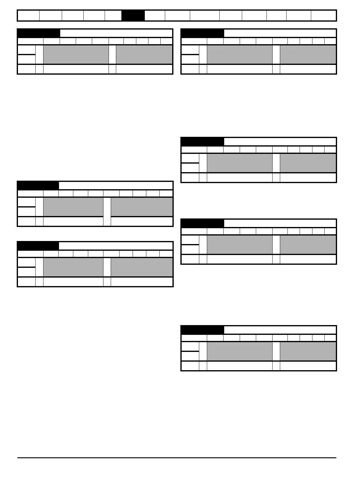
00.041 {05.071} Low Speed Sensorless Mode Current Limit
RW Num RA US
OL
Ú Ö
RFC-A
RFC-S
Ú
0.0 to 1000.0 %
Ö
20.0 %
00.042 {05.072} No-load Lq
RW Num RA US
OL
Ú
Ö
RFC-A
RFC-S
Ú
0.0000 to 500.000 mH 0.000 mH
00.043 {05.075} Iq Test Current For Inductance Measurement
RW Num US
OL
Ú Ö
RFC-A
RFC-S
Ú
0 to 200 %
Ö
100 %
00.044 {05.077} Phase Offset At Iq Test Current
RW Num RA US
OL
Ú Ö
RFC-A
RFC-S
Ú
±90.0 °
Ö
0.0 °
00.045 {05.078} Lq At The Defined Iq Test Current
RW Num RA US
OL
Ú Ö
RFC-A
RFC-S
Ú
0.000 to 500.000 mH
Ö
0.000 mH
00.046 {05.082} Id Test Current For Inductance Measurement
RW Num US
OL
Ú Ö
RFC-A
RFC-S
Ú
-100 to 0 %
Ö
- 50 %
00.047 {05.084} Lq At The Id Test Current
RW Num RA US
OL
Ú Ö
RFC-A
RFC-S
Ú
0.000 to 500.000 mH
Ö
0.000 mH