Description
2-9
Part 1602966−05
E 2015 Nordson Corporation
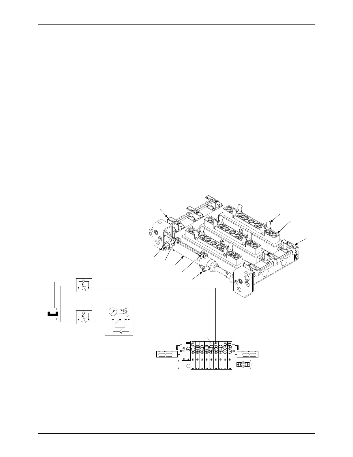
Purge Manifold
When the operator activates the gun purge mode during a color change
procedure, the lance assemblies are lowered onto the purge manifolds (1).
The latch cylinder (4) is extended, causing the latches (3) to clamp the
lances to the purge manifolds. Compressed air is then pulsed through the
lances, in-line pumps, feed hoses, and spray guns, one manifold at a time.
The purge sequence is controlled by the feed center PLC. Air is supplied by
the purge valves mounted on the back of the feed center.
The latch assemblies can be adjusted to change the clamping force exerted
on the lance assemblies, depending on the purge air pressure. Refer to the
Repair section, page 8-4, for adjustment procedures.
Clamping Cylinder Operation
Extend (Clamp): The extend air line is pressurized with regulated air,
forcing the cylinder rod out of the cylinder. The retract air line is vented.
Retract (Unclamp): The retract air line is pressurized with line air pressure,
forcing the cylinder rod into the cylinder. The extend air line is vented.
1
2
3
4
5
5
3
1
2
2
1
1
2
6 mm
6 mm
PURGE CLAMP
CYLINDER
FLOW
CONTROL
FLOW
CONTROL
REGULATOR
EXTEND
RETRACT
NINE-STATION CONTROL MANIFOLD
6
7
1
2345
6789
Figure 2-6 Purge Manifold Assembly (3 lance assembly shown with cylinder and latches in clamping position)
1. Manifold assembly
2. Lance guides
3. Latches
4. Latch cylinder
5. Piston proximity sensors
6. Extend flow control valve
7. Retract flow control valve

 Loading...


