Installation
3-13
Part 1602966−05
E 2015 Nordson Corporation
Damper Adjustment
The two-position damper is used to adjust the air flow that is drawn through
the feed center extraction duct.
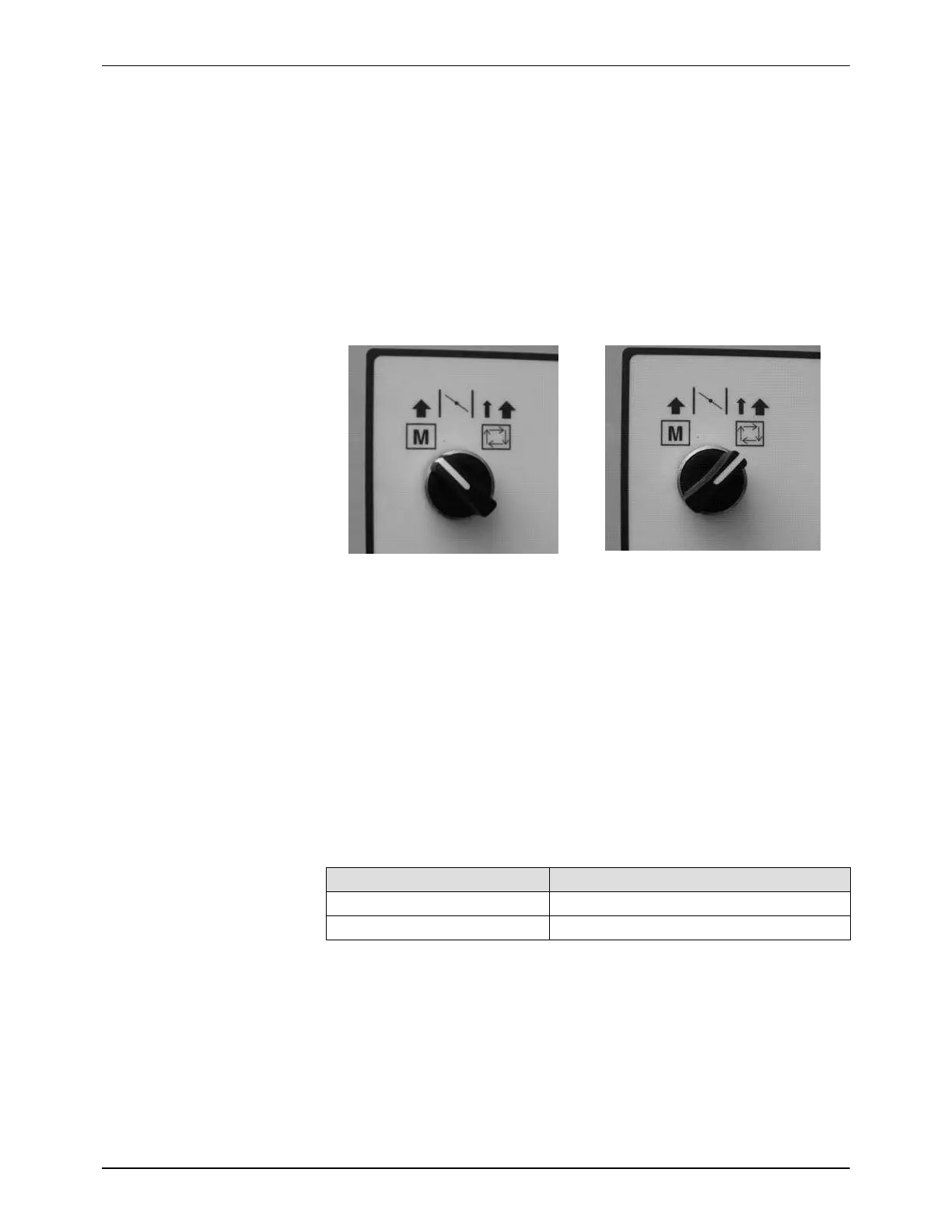
See Figure 3-21. When the damper selector switch is set to the automatic
position, the damper will automatically move to the high flow setting during
color change mode, and to the low flow setting during paint mode. When
the selector switch is set to the manual position, the damper will move to the
high flow position and remain there until the selector is moved back to the
automatic position.
Damper Selection − Manual Position
Damper Selection − Automatic Position
Figure 3-21 Damper Selection Switch Settings
The feed center air flow settings must be adjusted in the field during system
installation due to variations in system duct length and geometry. Use a hot
wire-type anemometer to adjust the damper settings. A reading should be
taken in the longest straight section of the 10 in. ductwork in order to obtain
the least influence from air turbulence.
NOTE: A qualified technician with experience in accurate duct flow
measurement techniques should perform this task.
See Table 3-2 for exhaust air flow ranges.
Table 3-2 Exhaust Air Flow Settings
Mode Air Flow Range
Color change mode 3058 − 3228 m
3
/hr (1800 − 1900 CFM)
Paint mode 2039 − 2209 m
3
/hr (1200 − 1300 CFM)
See Figure 3-22. The damper is equipped with adjustable stops for high
and low flow settings (3, 4). These stops limit the movement of the crank
arm that is attached to the butterfly valve.
The crank arm is set at the factory to allow the butterfly valve to move from
completely closed to approximately half-way open. Depending on the
system ductwork, this may need to be adjusted to achieve the desired flow
range.

 Loading...


