Description
2-11
Part 1602966−05
E 2015 Nordson Corporation
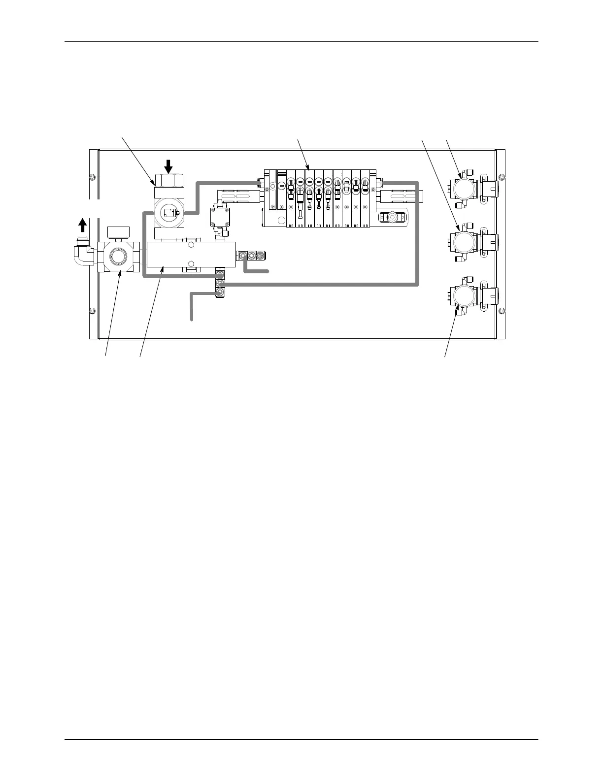
Pneumatic Panel Components
Refer to Figure 2-9 for an explanation of the 9-station control manifold
functions. Refer to Figure 11-1 for the feed center pneumatic diagram.
1
2
3
4
5 6
7
AIR IN
TO PURGE
VALVES
6-mm to Fluidizing Regulators
10-mm to Feed Center Blow Gun
10-mm
Figure 2-8 Pneumatic Components
1. Purge air regulator/gauge
2. Air manifold
3. Interlock valve
4. Control manifold
5. Lance UP regulator/gauge
6. Lance DOWN
regulator/gauge
7. Purge clamp regulator/gauge
Note: Refer to Section 4 Setup, and Section 5 Operation, for air pressure and control settings and usage.

 Loading...


