Repair
8-5
Part 1602966−05
E 2015 Nordson Corporation
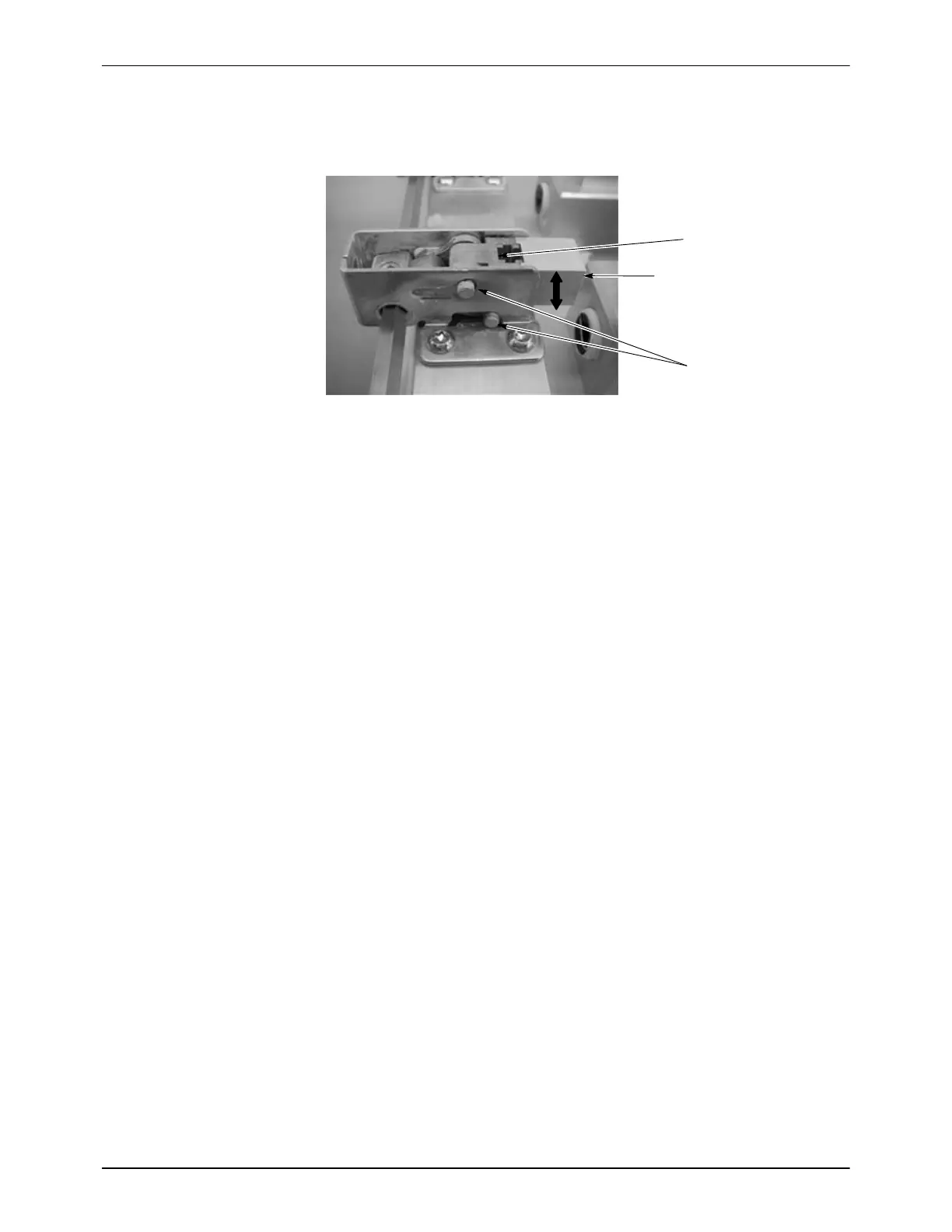
To reduce clamping force, the pawl can be moved up one notch. However,
do not do so if this allows the latch to go over-center when the lance is
clamped down.
3 Pins at end of travel,
over-center
1
2
Figure 8-4 Pawl Adjustment − Latch Shown Over-Center
1. Pawl mount
2. Pawl
3. Pins
Clamping Cylinder Replacement
1. Perform steps 1−3 in Latch Pawl Replacement.
2. See Figure 8-5. Disconnect the air tubing from the cylinder flow control
valves.
3. Retract the cylinder to gain access to the lever hardware.
4. Remove the clamp screws on each lever, then remove the cylinder and
lever assembly from the purge manifold yokes
5. Unsnap the clevis pin clips (2) and remove both clevis pins and levers.
6. Remove the proximity switches (5, 7) from the cylinder.
7. Remove the flow control fittings from the cylinder.
8. Remove both clevises and jam nuts from the cylinder.
9. Remove the cylinder adapter from the cylinder.
10. Install all the hardware and fittings removed from the old cylinder onto
the new cylinder. Install the proximity switches as follows:
S Extend (Engaged): LS403 − Install on rod end.
S Retract (Released): LS404 − Install on fixed end.
11. With the new cylinder rod retracted, install the cylinder onto the purge
manifold yoke assembly.
12. Push the cylinder rod into the cylinder until it is fully retracted. The
clevis pins should now be slightly loose in the levers. Rotate the
cylinder rod to thread it in or out of the rod end clevis and adjust the play
between the clevis pins and the levers. Tighten the locknuts.
13. Verify that when the cylinder is extended, the levers are making contact
with the clevises.

 Loading...


