Installation
3-11
Part 1602966−05
E 2015 Nordson Corporation
Lift Cylinder Proximity Switch Adjustment
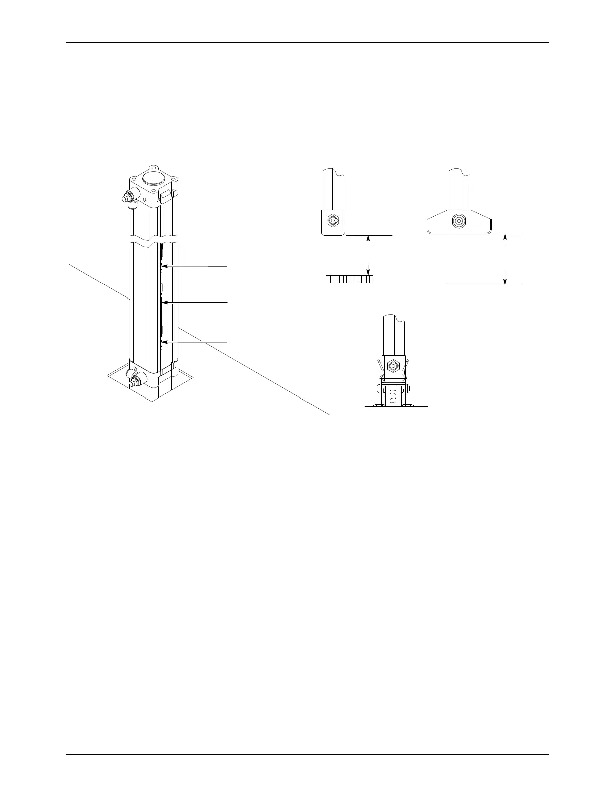
There are three proximity switches on the lift cylinder. They sense the
position of the cylinder piston, and therefore the bottom of the lance, in
relation to the hopper fluidizing plate, the bottom of a powder box, and the
purge manifold. Each switch has an LED that turns on when the switch is
closed through the use of a magnet embedded in the cylinder piston.
LS306
Hopper
LS307
Box
LS308
Purge
Hopper Box
Purge
1.0”
(25.4 mm)
1.0”
(25.4 mm)
Fluidizing Plate
Bottom of Box
Figure 3-19 Proximity Switches and Settings (Typical Lift Cylinder Shown)
NOTE: The lance assembly will stop at the Box or Hopper switch,
depending on the powder source selected. To override the switch, continue
to hold the Lance Control switch in the down position for 3 seconds after it
stops.
LS308 Purge Switch (Bottom Switch): Lower the lance down onto the
stop bolt. Slide the switch up and down while watching the LED. Mark the
positions at which the switch LED turns on in both directions, then secure
the switch midway between the on positions.
LS307 Box Switch (Middle Switch): Position an empty powder box on the
table. Lower the lance assembly down until it is at the recommended height
above the bottom of the box. Slide the switch up or down until the switch
LED turns on. Mark the positions at which the switch LED turns on in both
directions, then secure the switch midway between the on positions.
LS306 Hopper Switch (Top Switch): Position an empty hopper on the
table. Lower the lance assembly down until it is at the recommended height
above the fluidizing plate. Slide the switch up or down until the switch LED
turns on. Mark the positions at which the switch LED turns on in both
directions, then secure the switch midway between the on positions.

 Loading...


