Installation
3-6
Part 1602966−05
E 2015 Nordson Corporation
Pump Flow and Atomizing Air Tubing
See Figures 3-15 and 3-16. If the pumps are installed at the factory, the
flow (black) and atomizing (blue) air tubing is also installed from the pumps
to the air manifolds on the back wall of the feed center. If not, the pumps
are numbered and the tubing must be connected from the pumps to the
appropriate fittings in the air manifolds on the back wall of the feed center.
Powder Feed Hose Connections
See Figures 3-15 and 3-16. Label and route the powder feed hoses (5)
from the spray guns through the multi-tube PVC grommets (7) on the back
wall of the feed center and connect the hoses to the appropriate pump
outlet fittings (1). Refer to your system drawings for the correct
connections.
Hose and Tubing Counterweighting
See Figure 3-16. Allow enough slack in the hoses (5) and air tubing (3, 4)
to allow the lance assembly to travel through its full range of movement
without stretching or kinking the hoses or tubing. Bundle the hoses and
tubing with the provided Velcro straps (10) to prevent kinking or damage,
then attach the strap to the counterweight assembly (6).
The counterweight assembly is shipped with six weights. Use two weights
for each lance assembly.
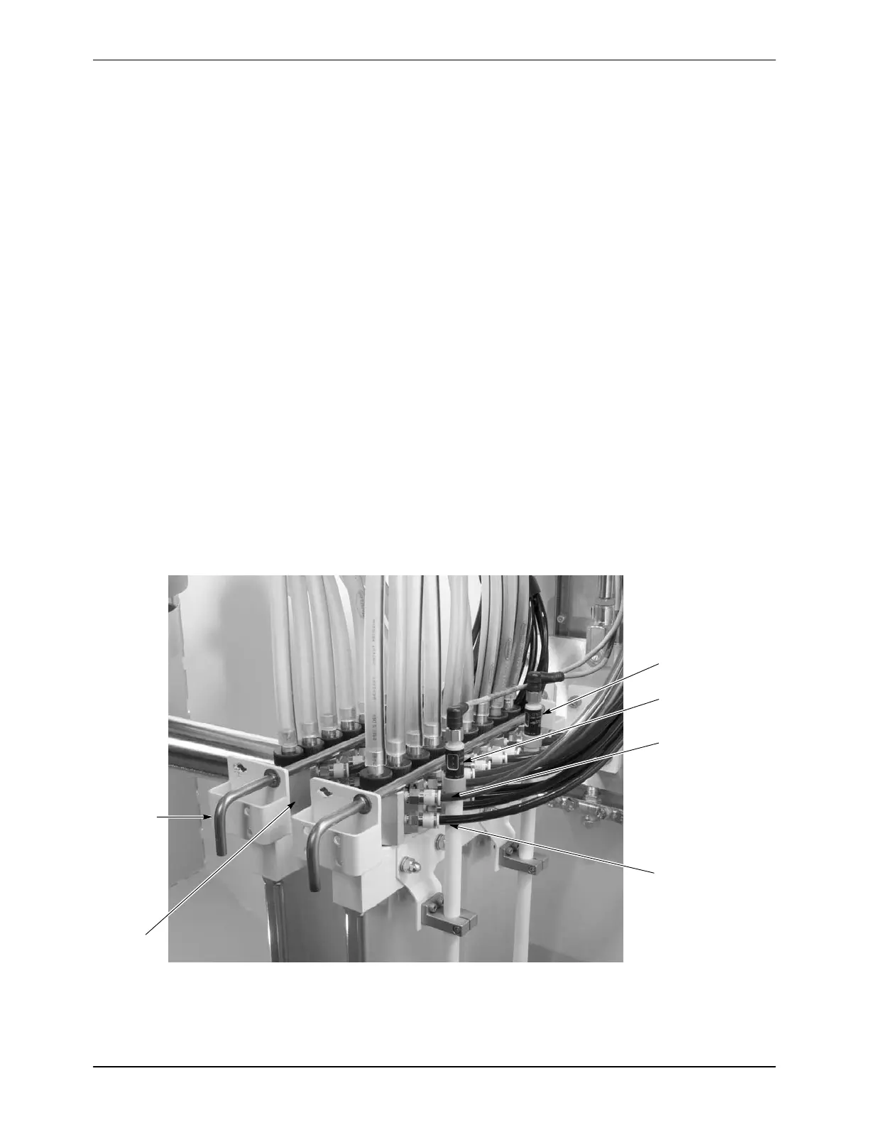
Flow-rate Air
(8-mm Black)
Atomizing Air
(8-mm Blue)
Level Sensor
(Box)
Level Sensor
(Hopper)
Pump
Pump
Retainer
Figure 3-15 Pump, Air Tubing, and Powder Feed Hose Installation

 Loading...


