Repair
8-4
Part 1602966−05
E 2015 Nordson Corporation
Latch Installation (contd)
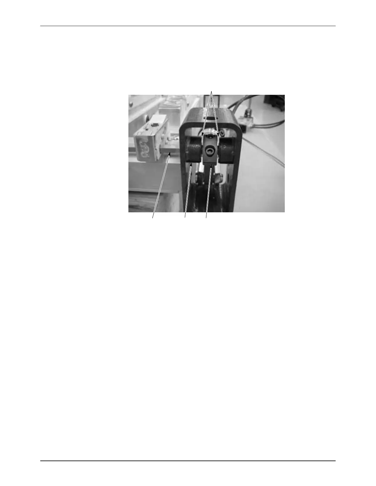
4. See Figure 8-3. If all latches have been removed from the hex shaft,
push or pull on the hex shaft (4) to center the lever (2) in the yoke (1)
before you tighten the set screw to secure the latch to the hex shaft.
3 2
1
Gap should be equal both sides
Figure 8-3 Lever Position − Step 4
1. Yoke
2. Lever
3. Hex shaft
5. After all latches have been re-installed, check the latch movement by
extending and retracting the clamping cylinder by hand. The pawl
should move freely side-to-side and not bind on the sides of the latch
body when the latch is extended and retracted.
If the pawl binds against the sides of the body, loosen the four latch
mounting screws, then push outwards on the sides of the latch body
while re-tightening the screws.
Latch Pawl Adjustment
Figure 8-4 shows a latch extended until it is over-center. The latch pawl (2)
is normally installed with the top surface flush with the top surface of the
pawl mount (1). With the lance clamped down, the latch should not go
over-center (fully extended). The latch pins (3) should not be up against the
ends of their slots.
If the latch does go over-center, the latch pins make a clicking noise when
they hit the ends of the slots.
To reduce latch travel and increase clamping force, loosen the Philips-head
screw in the pawl recess and move the pawl down one notch. This
adjustment may also be required with higher purge air pressures to increase
the clamping force.

 Loading...


