Installation
3-14
Part 1602966−05
E 2015 Nordson Corporation
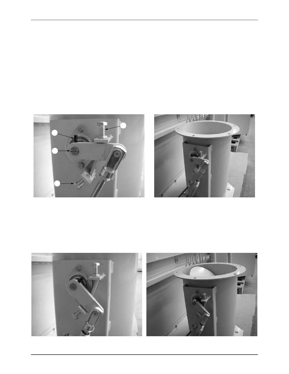
Damper Adjustment (contd)
The crank arm can be moved in relation to the butterfly valve. To do this,
loosen the crank arm set screw (1), adjust for the new position, and
re-tighten the set screw. An indicator mark inscribed on the end of the
butterfly valve shaft indicates the butterfly valve position (2).
NOTE: All crank arm adjustments must be done with the afterfilter fan in
the OFF position.
Figure 3-22 shows the damper in the factory-set low flow, or closed,
position. The butterfly valve position is indicated by the indicator mark (2),
which is shown in a horizontal position.
1
2
3
4
Figure 3-22 Damper Setting, Factory-Set Low Flow Position
1. Crank arm set screw
2. Butterfly valve position indicator
3. High flow adjustable stop 4. Low flow adjustable stop
Figure 3-23 shows the damper in the factory-set high flow position. The
damper can be seen approximately half-way open, and the butterfly valve
position indicator mirrors the angle of the damper, showing that it is open.
Figure 3-23 Damper Setting, Factory-Set High Flow Position

 Loading...


