Installation
3-15
Part 1602966−05
E 2015 Nordson Corporation
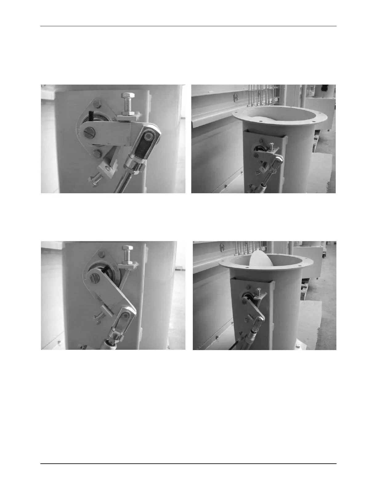
Figure 3-24 shows the damper in an adjusted low flow position, which has
been set slightly higher than the factory setting. The crank arm has been
adjusted in relation to the butterfly, which is noted by the indicator line being
at an angle similar to the new damper position.
Figure 3-24 Damper Setting, Adjusted Low Flow Position
Figure 3-25 shows the damper in an adjusted high flow position. Note that
the indicator is now almost vertical, as is the new damper position.
Figure 3-25 Damper Setting, Adjusted High Flow Position

 Loading...


