6-4 Service Manual
XZAC4219-05
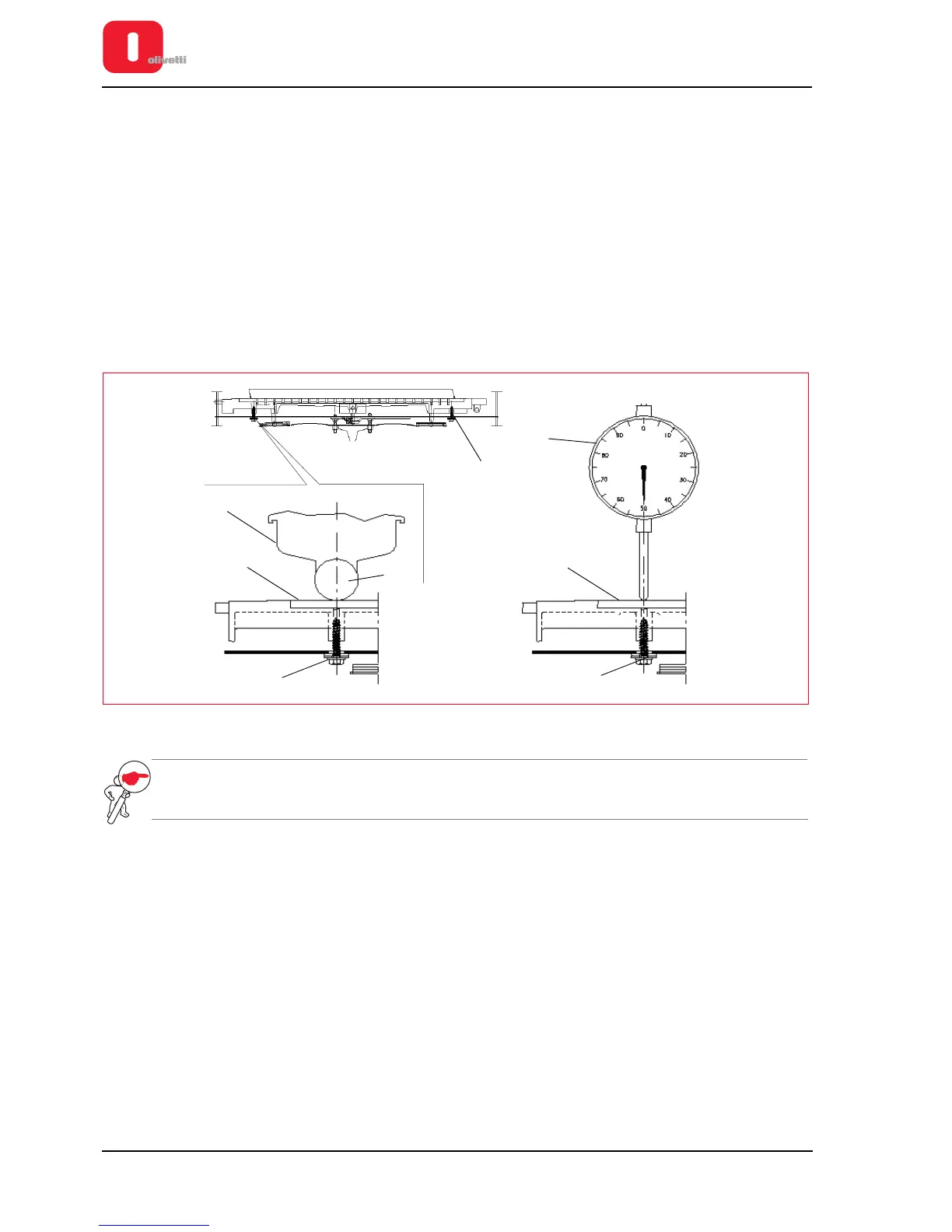
Adjusting the print bar (where torsion bar present)
• MACHINE STATUS
– Printer switched off and without casing.
– Printhead positioned co-axially with the axis of the screw used to make the adjustment.
• CONDITIONS TO BE CHECKED
Distance of 0.4 - 0.5 mm between print bar (2) and feeler roller (3).
• PROCEDURE
– Disassemble the mechanical unit. See the section “Mechanical assy disassembly/reassembly” on page 7 - 6.
– Bring the print unit to the writing position; then, using the two screws (1), adjust the print bar (2) in contact
with the feeler roller (3), positioning the head (4) in axis with the screw.
– Lift the print unit and move the print bar (2) up by 0.35 - 0.45 mm, operating on the screw (1) and checking
movement with a comparator (5) positioned on the axis of the screw.
– Repeat the operation on the other screw, from the opposite side of the structure.
Figure 6 - 3 Adjusting the print bar
NOTE: check the print quality with OFF-LINE testing. See the section “Activating and deactivating the print
test” on page 2 - 10.