XZAC4219-05 Service Manual
1-5
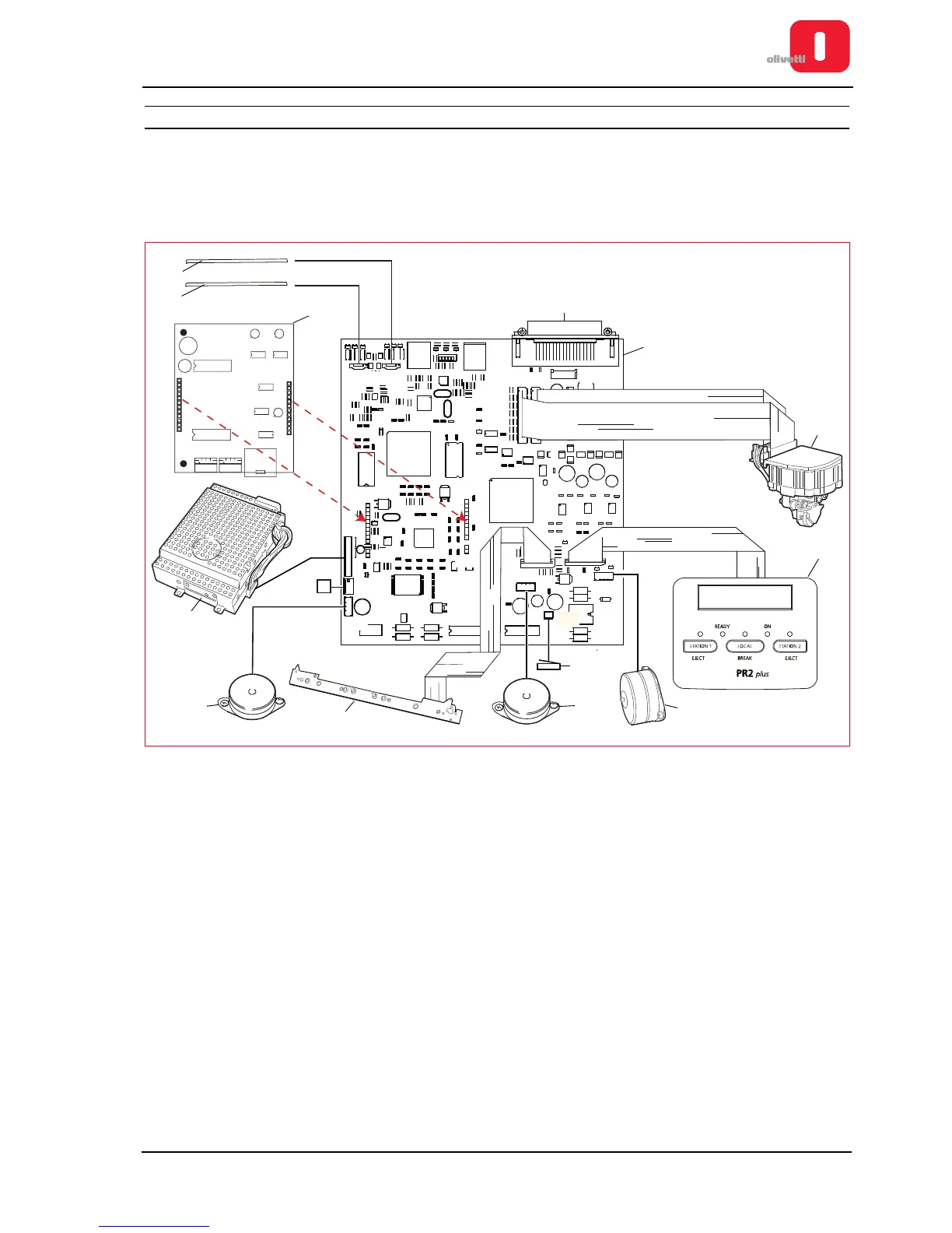
GENERAL BLOCK DIAGRAM
The schema represented in the following figure illustrates the most complete version of the printer, with all the
options and including the scanner. For other versions of the motherboard used for the PR2 Plus printer, only the
connectors will be indicated.
In the following schema are indicated also the connectors for connecting the peripherals and the motherboard.
Figure 1 - 4 Block Diagram
1 Front CIS 8 Paper feeder motor
2 Back CIS 9 Cover sensor
3
Magnetic options interface
(Horizontal Magnetic or MICR)
10 Paper presence/alignment photosensors
4 Motherboard (Version with scanner) 11 Services motor
5 Printhead 12 Power supply unit
6 Console 13 Front paper present photosensor
7 Printhead carriage motor