XZAC4219-05 Service Manual
7-11
Upper mechanical assy disassembly/reassembly
1. Disassembling the casing. See the section “Casing disassembly/reassembly” on page 7 - 4.
2. From the front, lift the entire mechanical assy from the base plate and rotate it partially so as to access the
connectors of the motherboard.
See the section “Mechanical assy disassembly/reassembly” on page 7 - 6.
3. Disconnect the connection cables of the printhead, of the carriage reset photosensor and of the upper scanner
CIS (if present) from the motherboard. Free the cable of the carriage reset photosensor from the plastic clips.
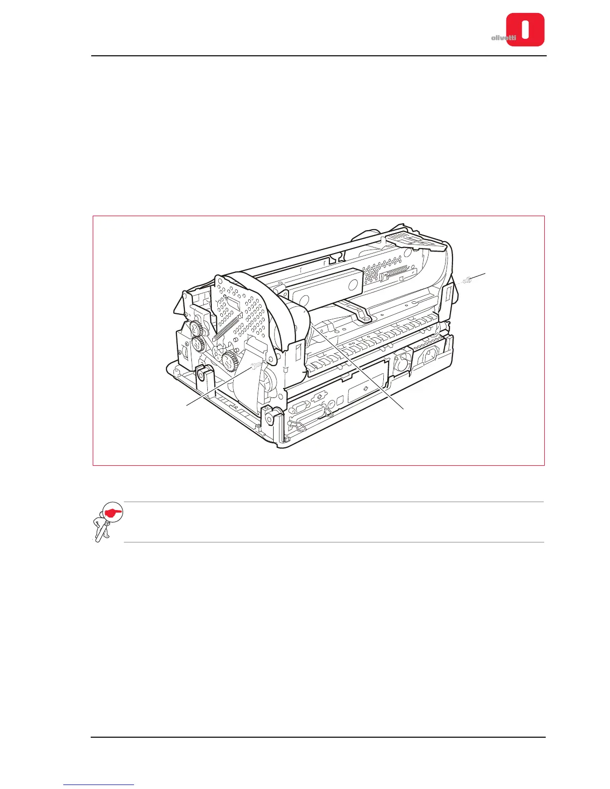
4. Disconnect the connector (1) from the carriage transport motor.
5. Lift the upper mechanical assy using the specific levers. See the section “Lever for lifting the upper part of the
mechanism” on page 3 - 4.
6. Back off the two rear side hinge pins (2) to disconnect the upper mechanical assy.
Figure 7 - 13 Disassembling the upper mechanical assy
NOTE: during reassembly, make sure that the cables are passed through the related compartments and
check adjustment of the roller gear.
See the section “Adjusting the roller gears” on page 6 - 9.