Definitions of Basic Terms
8
Vision System FH/FHV/FZ5 Series User’s Manual (Z365)
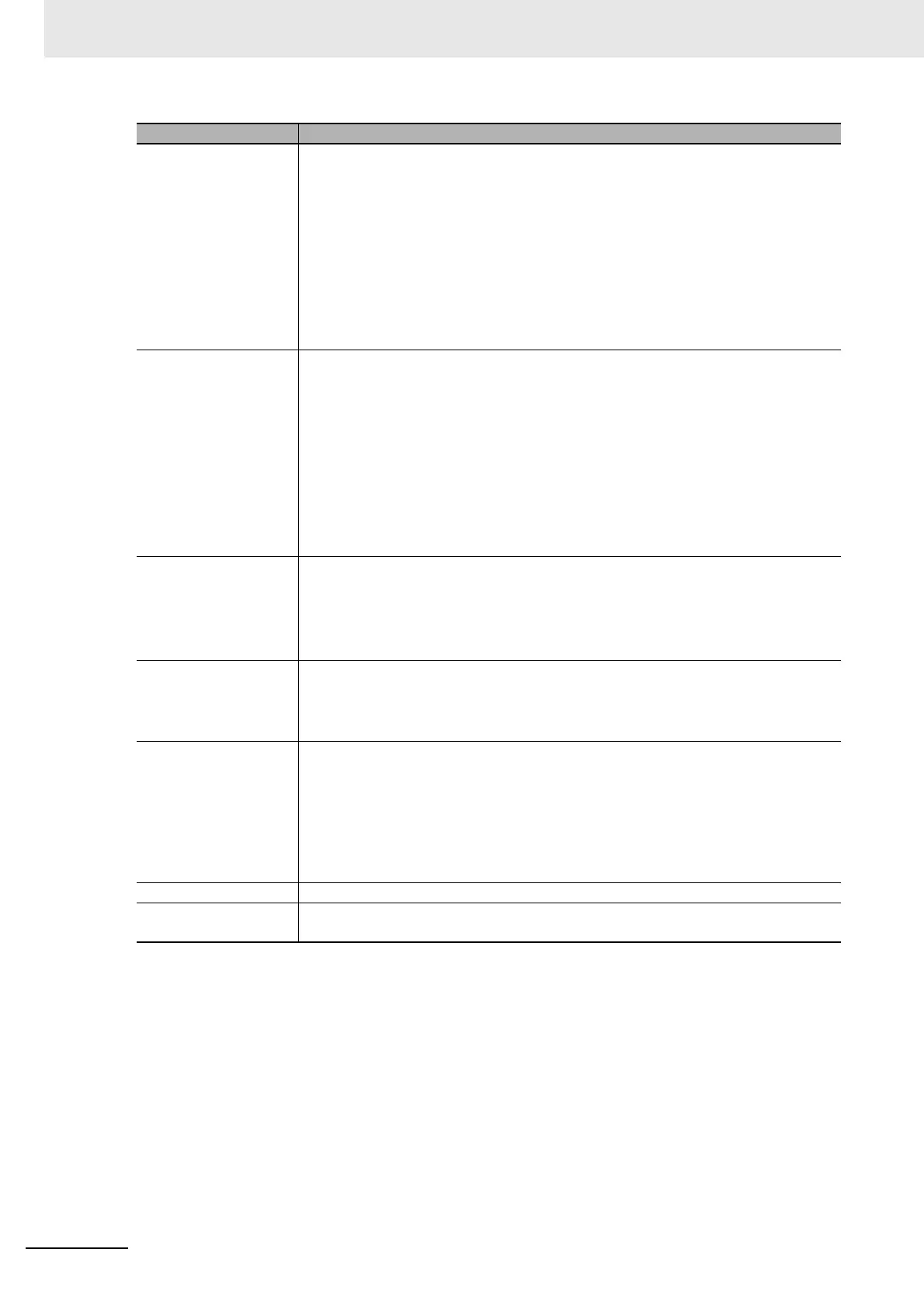
processing item Any of the individual items for vision inspections that are partitioned and packaged so
that they can be flexibly combined.
These include the Search, Position Compensation, and Fine Matching items.
Processing items can be classified for image input ([Input image]), inspection/mea-
surement ([Measurement]), image correction ([Compensate image]), inspection/mea-
surement support ([Support measurement]), process branching ([Branch]), results
external output ([Output result]), resulting image display ([Display result]), etc.
You can freely classify processing items to handle a wide range of applications.
A scene (i.e., a unit for changing the measurement flow) is created by registering the
processing items as units.
scene A unit for changing the measurement flow that consists of a combination of processing
items.
“Scene” is used because of the correspondence to the scene (i.e., type of measure-
ment object and inspection contents) where measurements are performed.
A scene is created for each measurement or measurement contents.
You can easily achieve a changeover simply by changing the scene when the mea-
surement object or inspection content changes.
Normally you can set up to 128 scenes. If you need more than 128 scenes, you can
separate them into different groups or use the Conversion Scene Group Data Tool to
create a scene group that contains over 128 scenes.
processing unit (abbre-
viated as “unit”)
A processing item that is registered in a scene.
Numbers are assigned to processing units in order from the top and they are executed
in that order.
Processing items are registered for the processing units to create a scene (i.e., a unit
for changing the measurement flow).
measurement trigger A trigger for executing measurements.
With a parallel interface, the STEP signal or command 00 (Continuous Measurement)
is used. With a serial interface, an Execute One Measurement or a Start Continuous
Measurement command is used.
test measurement A measurement that is performed to manually test (check) measurements under the
conditions that are set in the currently displayed scene.
Test measurements can be executed on an Adjustment Window. Processing is com-
pleted inside the Controller and the measurement results are not normally output on
an external interface.
However, you can select [Output] in [Test measurement] to output the measurement
results after executing measurements.
single measurement A measurement that is executed only once in synchronization with the trigger input.
continuous measure-
ment
Measurements are executed repeatedly and automatically without a trigger input.
Term Definition
 Loading...


