4 - 11
4 Setting the Controller
Vision System FH/FHV/FZ5 Series User’s Manual (Z365)
4-3 Setting Communication [Startup Settings]
4
There are two types of connections for touch panel communication: USB connection and RS-232C con-
nection.
Normally use a USB connection for the touch panel.
Use an RS-232C connection in the following cases.
• The Touch Panel Monitor (FH-MT12) and the FH series Sensor Controller are more than 5 m apart.
• All the USB ports of the FH series Sensor Controller are used for other I/O connections, and thus
there is no available USB port for the Touch Panel Monitor (FH-MT12) connection.
Note that following restrictions apply to each type of communication.
• If the Touch Panel cable (USB or RS-232C) is accidentally slipped out during FH series Sen-
sor Controller is running, cannot operate the Touch Panel even if you try to re-connection the
cable. For continue to operation or perform, connect a wired USB mouse which is not need to
install driver.
• To re-operate the Touch Panel, confirm the connection Touch Panel Monitor FH-MT12 and
FH series Sensor Controller, and then retry to initiate the Sensor Controller.
For detail of OSD (On-screen display), refer to Model FH-MT12 Touch Panel Monitor
INSTRUCTION SHEET.
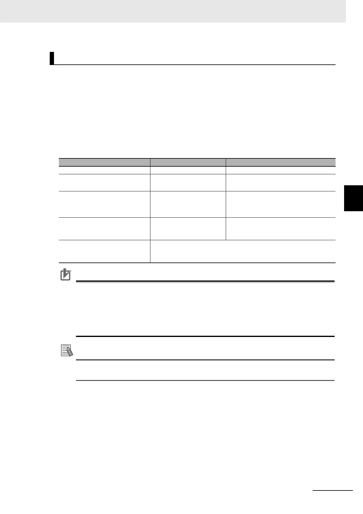
Difference in Touch Panel Monitor Communications
Subject USB connection RS-232C connection
Cable length 2 m or 5 m 2 m, 5 m, or 10 m
Communication module setting on
FH series Sensor Controller
No setting required Serial (RS-232C/422) setting
required
Startup order for Touch Panel Moni-
tor and FH series Sensor Controller
No restriction 1. Connect cables
2. Start the Touch Panel Monitor
3. Start the FH series Sensor Controller
Startup time of FH series Sensor
Controller without touch panel cable
connected
Standard 30 seconds longer
Resulting behavior when simultane-
ously using both USB connection
and RS-232C connection.
The USB connection overrides the RS-232C connection.

 Loading...

