4 - 23
4 Setting the Controller
Vision System FH/FHV/FZ5 Series User’s Manual (Z365)
4-4 Setting Operation Mode [Startup Settings]
4
4-4-1 Setting the Operation Mode
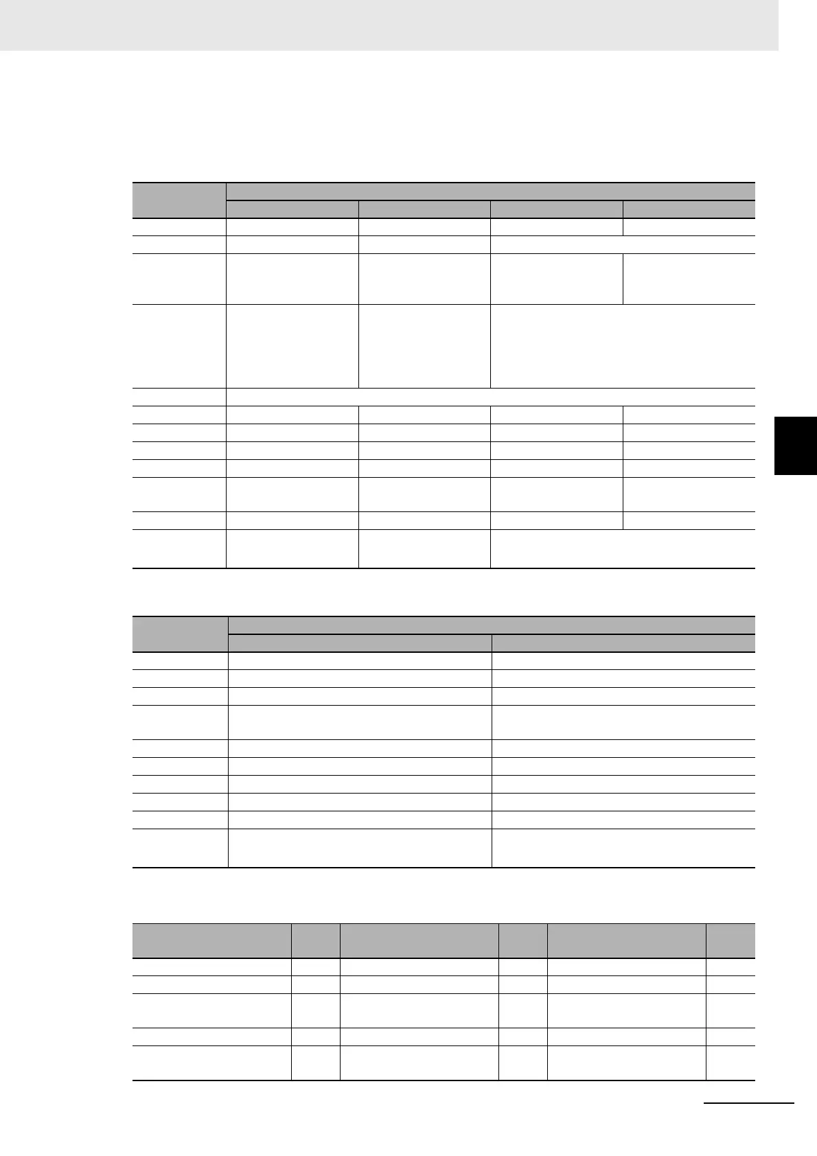
Table 1: Parallel I/O Functions and Parallel Terminals for Multi-line Random-
trigger Mode
• FH-1000/3000/5000 series
• FZ5-800/1100/1200 series
The following processing items are supported in the multi-line random trigger mode:
I/O
Number of lines
1 line 2 lines 3 to 4 lines 5 to 8 lines
STEP STEP0 STEP0 or STEP1 STEP0 to STEP3 STEP0 to STEP7
DSA DSA0 DSA0 or DSA1 No output
DI DI0 to DI7 DILINE0, DI0 to DI7
(shared by all lines)
DILINE0 to DILINE1,
DI0 to DI7 (shared by
all lines)
DILINE0 to DILINE2,
DI0 to DI7 (shared by
all lines)
ENC (phases
A, B, and Z)
ENC0 phase A, ENC0
phase B, and ENC0
phase Z
ENC0 phase A, ENC1
phase A, ENC0 phase
B, ENC1 phase B,
ENC0 phase Z, and
ENC1 phase Z
No output
ACK ACK (shared by all lines)
RUN RUN0 RUN0 or RUN1 RUN0 to RUN3 No output
GATE GATE0 GATE0 and GATE1 No output
BUSY BUSY0 BUSY0 or BUSY1 BUSY0 to BUSY3 BUSY0 to BUSY7
OR OR0 OR0 or OR1 OR0 to OR3 OR0 to OR7
ERROR ERROR0 ERROR0 or ERROR1 ERROR0 to ERROR3 ERROR (shared by all
lines)
READY READY0 READY0 or READY1 READY0 to READY3 READY0 to READY7
DO DO0 to DO15 Line 0: D00 to D07
Line 1: D8 to D15
No output
I/O
Number of lines
1 line 2 lines
STEP STEP0 STEP0 or STEP1
DSA DSA0 DSA0 or DSA1
DI DI0 to DI7 DI0 to DI7
RUN RUN None (This input is assigned as the BUSY sig-
nal for line 1.)
GATE GATE0 GATE0 and GATE1
BUSY BUSY BUSY or RUN
OR OR0 OR0 or OR1
ERROR ERROR ERROR (shared by all lines)
READY READY0 READY0 or READY1
DO DO0 to DO15 Line 0: D00 to D07
Line 1: D8 to D15
OK:Supported processing item, RST: Processing item with restricted support, ---:Unsupported processing item
Processing item
Sup-
port
Processing item
Sup-
port
Processing item
Sup-
port
Camera Image Input OK Stripes Removal Filter II OK Data Save OK
Camera Image Input FH OK Glue Bead Inspection OK Statistics OK
Camera Image Input FHV
---
Position Compensation
OK
Calibration Data Refer-
ence
OK
Camera Image Input HDR OK Filtering OK Position Data Calculation OK
Camera Image Input HDR
Lite
OK
Back Ground Suppression
OK
Stage Data
OK
 Loading...


