4 Setting the Controller
4 - 28
Vision System FH/FHV/FZ5 Series User’s Manual (Z365)
Normally, the sensor controller executes measurements, image logging, and image display in a desig-
nated order. The FH series/FZ5-800/1100/1200 series execute those processes with one of the CPU
cores, and uses the rest of the cores for measurement processing. This ensures that measurements
are always processed at maximum performance.
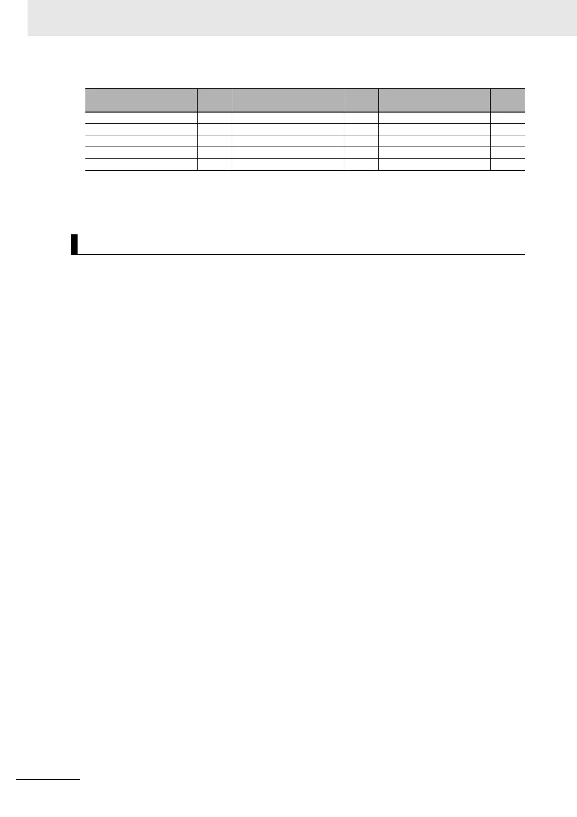
Intersection OK Position Data Calculation OK Manual Position Setting ---
Barcode OK Stage Data OK 2DCode II OK
Glue Bead Inspection OK Robot Data OK Result output (I / O) OK
Position Compensation OK Vision Master Calibration --- Result output (Message) OK
Filtering OK PLC Master Calibration ---
*1. The [Subt./Reg.] and [DI Register] measurement modes are not supported.
*2. Sensor Controller in Non-Stop Adjustment Mode does not stand by.
*3. Re-measured images in Non-Stop Adjustment Mode are logged.
Standard (Operation Mode)
OK: Supported processing item, RST: Processing item with restricted support, ---: Unsupported processing item
Processing item
Sup-
port
Processing item
Sup-
port
Processing item
Sup-
port

 Loading...

