10 - 11
10 Advanced Usage
Vision System FH/FHV/FZ5 Series User’s Manual (Z365)
10-1 Remotely Operating the Controller
[Remote Operation]
10
10-1-2 Connection Method for Remote Operation
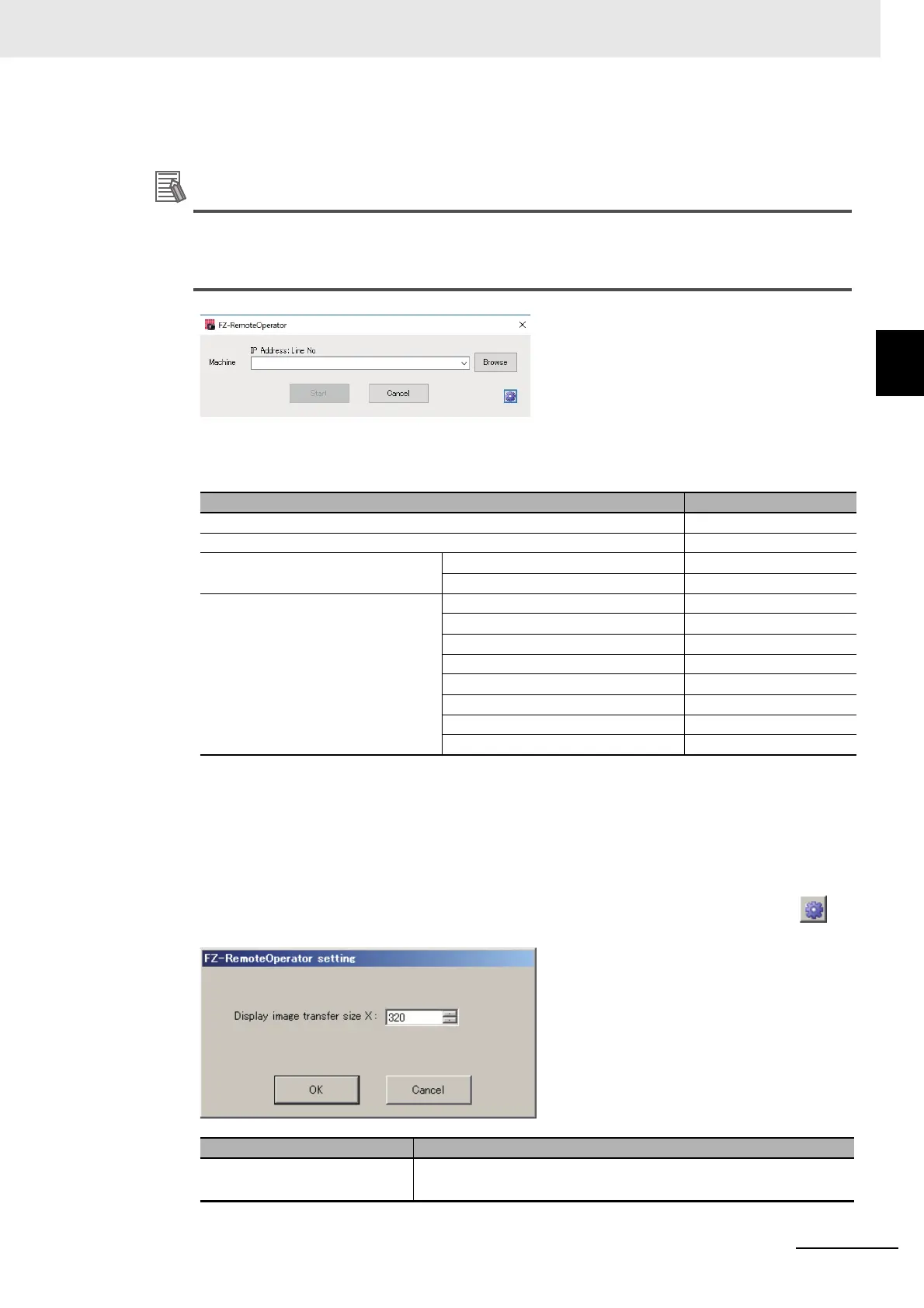
5 In the dialog displayed in the "Remote Operation Tool", select or directly input the IP address
and "Line No." for the Sensor Controller to be connected.
Click [Browse] to check the IP addresses and Line numbers for connectable sensor controllers.
If the network address of an IP address were different from a remote operation PC, the remote
operation cannot be connected even if the PC is displayed in the list.
The "Line No" selected here is one of the following based on the system's operation mode.
*1. The FZ5-800/1100/1200 series Sensor Controller always has two lines (Line 0 and1), and the FH
series Sensor Controller is capable to have up to eight lines. Set the line number based on the num-
ber of lines set in the Sensor Controller.
If a line number other than the above was selected, the remote operation cannot be connected
to Sensor Controllers.
6 Change the size of an image to transfer with the remote operation as necessary. Select ( ) to
set.
Operation mode Setting
Standard Line No = 0
Double Speed Multi-input Line No = 0
Non-stop adjustment Measurement window Line No = 0
Non-stop adjustment window Line No = 1
Multi-line random trigger
*1
Line 0 side Line No = 0
Line 1 side Line No = 1
Line 2 side Line No = 2
Line 3 side Line No = 3
Line 4 side Line No = 4
Line 5 side Line No = 5
Line 6 side Line No = 6
Line 7 side Line No = 7
Setting item Description
Display image transfer size
(Size of the image to transfer)
Sets the width of the image displayed in the remote operation window.
(default: 320)
 Loading...


