A - 3
Appendices
Vision System FH/FHV/FZ5 Series User’s Manual (Z365)
A-1 Menu List
A
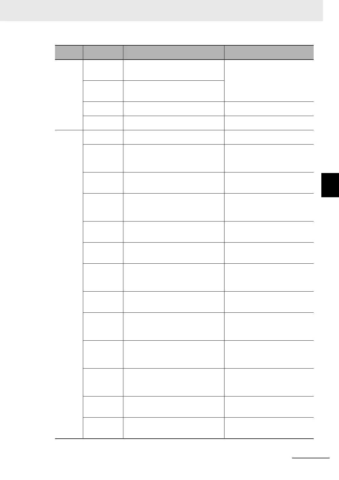
Function Transfer data Transfers (copies) the settings for line 0 to
line 1, and then changes to the Non-stop
Adjustment Mode.
Refer to Non-stop Adjustment Mode
on page 4-25.
Non-stop data
transfer
Transfers (copies) the settings for line 1 to
line 0 in Non-stop Adjustment Mode with-
out affecting measurements.
Operation log Saves the operation log of the Controller to
a special file.
Refer to 10-4-1 Using the Operation
Log on page 10-40.
System infor-
mation
Displays the Controller’s model and soft-
ware version.
Refer to 3-3 Checking System Infor-
mation on page 3-27.
Tool TDM Editor Edits the processing flow using variables. Refer to 5-5 Using Variables to Edit
the Flow [TDM Editor] on page 5-14.
System Set-
tings
Sets settings that are related to the system
environment of the Controller. Includes
settings such as the startup settings, Cam-
era settings, and communications settings.
Refer to Section 4 Setting the Con-
troller on page 4-1.
Security set-
tings
Used to set accounts and limit access to
the Controller.
Refer to 10-3 Limiting User Opera-
tions [Security Settings] on page
10-29.
Scene Group
Saving Desti-
nation Settings
Changes the location for saving scene
group data to the sensor controller’s mem-
ory or external storage.
Refer to 7-5 Saving Scene Groups in
External Storage [Scene Group Sav-
ing Destination Settings] on page
7-10.
NG analyzer Used to analyze NG causes based on
image data.
Refer to 6-5 Analyzing Inspection and
Measurement Results [NG Analyzer]
on page 6-29.
User data tool Sets the initial value for user data that can
be shared across scenes and across
scene groups.
Refer to A-12 Sharing Data Within
the Controller [User Data Tool] on
page A-37
Settings down-
load and
upload tools
Used to download and upload a list of set
values for scene data as a CSV file.
Refer to 9-10 Outputting a list of
Scene Data Setting Values [Setting
Values Download/Upload Tools] on
page 9-51.
Layout down-
load and
upload tools
Saves the layout settings of the Main Win-
dow in a file and loads the settings.
Refer to 9-11 Saving/Loading Layout
Settings [Layout Upload, Download
Tool] on page 9-55.
Image file save Saves logged images and image files that
are saved in the Controller.
Refer to 9-9 Saving Image Files to a
RAMDisk or an External Storage
Device [Image File Save] on page
9-48.
Registered
Image Manager
Used to register the most recent input
image, a logged image that is saved in the
Con
troll
er or an image file and load it as a
measurement image.
Refer to 6-7 Managing Images used
for Model Registration and Reference
[Registered Image Manager] on page
6-42.
Communica-
tion Command
Marco
Creates a communication unit (Communi-
cation custom command) customized by
user for FH/FHV/FZ5 series from external
devices such as PLC.
Refer to 10-7 Customizing Communi-
cation Commands [Communication
Command Macro] on page 10-47.
Flow viewer Shows the flow of processing for the mea-
surement flow that is currently being
edited.
Refer to 5-4 Displaying and Checking
Processing Branches in a Scene on
page 5-10.
Calibration sup-
port tool
Graphically displays the relationship of the
positions of the Camera coordinates and
the actual coordinates.
Refer to 6-8 Verifying Calibration
Results [Calibration Support Tool] on
page 6-47.
Main
menu
Command Description Reference
 Loading...