Setting up Compax3 C3I22T11
194 192-120114 N5 C3I22T11 June 2008
face of the ideal system, the approximated system can be described, up to a cer-
tain frequency, with the transmission function of the P-T1 component.
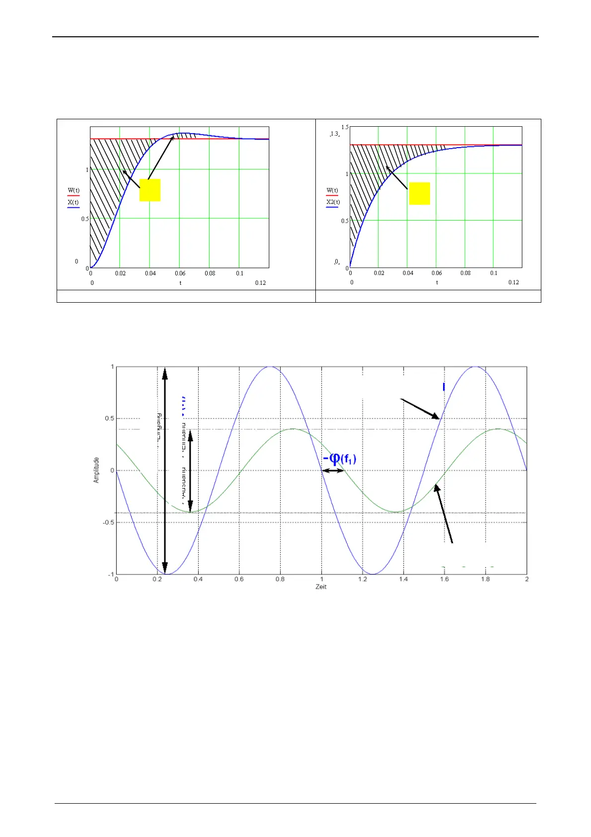
Determination of the control surface from the transmission behavior of a P-TE component.
Kp
1
+
-
Kp
1
1: Control surface of the approximated system 2: Control surface of the ideal P-T1 component
The velocity of a dynamic system can also be described in the frequency range. In
the frequency range, the system behavior is analyzed to sinusoidal inputs signals
of different frequencies (frequency response).
Input and output signals of a dynamic transmission component at a defined fre-
quency f=f1
Input Signal
Eingangs-Signal
Output Signal
usgangs-Signal
Innal
Output Signput Signal(f1)
The bode diagram represents the behavior of a dynamic system (in our case of the
P-TE component) against the input signal frequency with respect to amplitude and
phase.

 Loading...


