Setting up Compax3
C3I12T11
192-120113 N08 C3I12T11 - December 2010
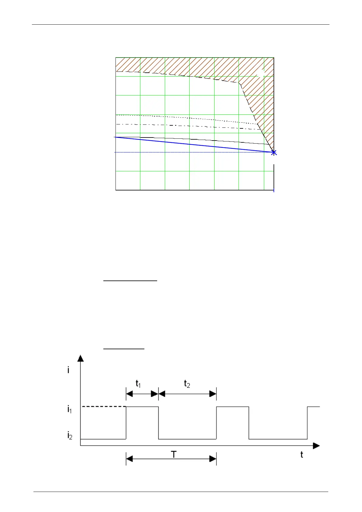
Reference point 1: higher velocity at reduced torque
0 500 1000 1500 2000 2500 3000
0
0.5
1
2
2.5
3
3.5
S1 65°C DT
S3 50% 65°C DT
S3 20% 65°C DT
S1 105°C DT
[A]
[1/min]
22
I
0
n
1
I
1
rp1
I
0
: Standstill current
rp1: Reference point 1 (defined in the C3 ServoManager)
I
1
: Reference current to reference point 1
n
1
: Reference velocity to reference point 1
2: Forbidden range
For monitoring the continuous usage, the linearized characteristic line between I
0
and I
1
/ n
1
is used as a threshold.
Motor pulse usage
This monitoring watches over the duration of the defined pulse current. The
permitted duration for the pulse current is defined by the pulse current time
constant.
If the acceleration current exceeds the nominal current for a defined time t1, a
sufficient break time t2 is required. If the current remains in average above the
nominal current, the "monitoring motor pulse usage" [0x7180] error is triggered.
Upon a high pulse usage, the error will occur almost without delay.
Current cycle: