Setting up Compax3
C3I12T11
192-120113 N08 C3I12T11 - December 2010
Stability problem in the high-frequency range:
The "control structure" figure shows that the reverse effect in the control loop
(negative feedback) is a prerequisite for the functioning of a control system. Due to
the delay in signal transmission, the effect of the negative feedback is diminished
or even compensated. The reason is that the corrective measures of the controller
are also delayed in the event of delayed signal transmission. This results in a
typical oscillating course of the control variable. In the worst case, the deviation of
the control variable and the effect of the corrective measures get in phase, if the
delays reach a defined value. The negative feedback passes into positive
feedback. If the product of the gain factors of all control loop components is higher
than 1, the oscillation amplitude will continually rise.
In this case the control loop is unstable. In the total gain of 1 the oscillation keeps
its amplitude and the control loop is within the limits of stability. The transient
response can be characterized by the attenuation and the transient time (velocity).
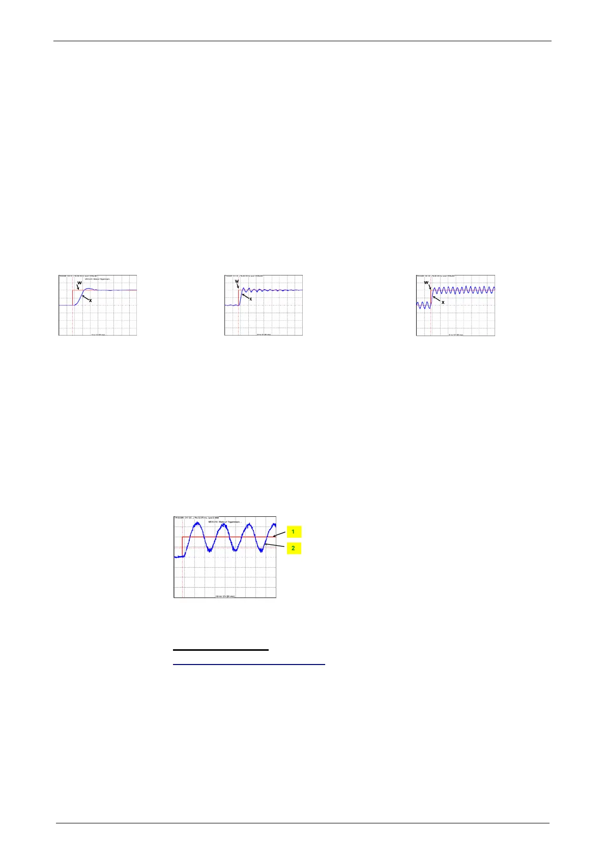
Step response of a stable controller and of a controller approaching the stability limit
Rugged
Well attenuated
Rugged
Poorly attenuated
Stability limit
not attenuated
W: Setpoint value
x: Actual value
Stability problem in the low-frequency range:
In this case the controller was set for a very inert control path, while the actual
control path is much more dynamic. The controller reacts to a disturbance variable
with a much too strong corrective measure so that the disturbance variable is
overcompensated and even an increasing oscillation may be the result. In this case
the mechanic system of the control path may be destroyed.
Velocity jerk response (low-frequency stability limit)
1: Setpoint speed value
2: Actual speed value
Velocity, bandwidth
In this chapter you can read about:
P-TE - Symbol ............................................................................................................... 195
Step response of a delay component ............................................................................. 195
Approximation of a well-attenuated control loop ............................................................. 195
Frequency response of the P-TE component (value and phase) .................................... 197
A well attenuated control loop can, under certain conditions, be approximated in
order to simplify the controller design with a first order delay component (P-TE
component) with the replacement time constant TE and the total gain Kp. A P-TE
component represents a first order delay component and is a simple dynamic basic
component.