Setting up Compax3
C3I12T11
192-120113 N08 C3I12T11 - December 2010
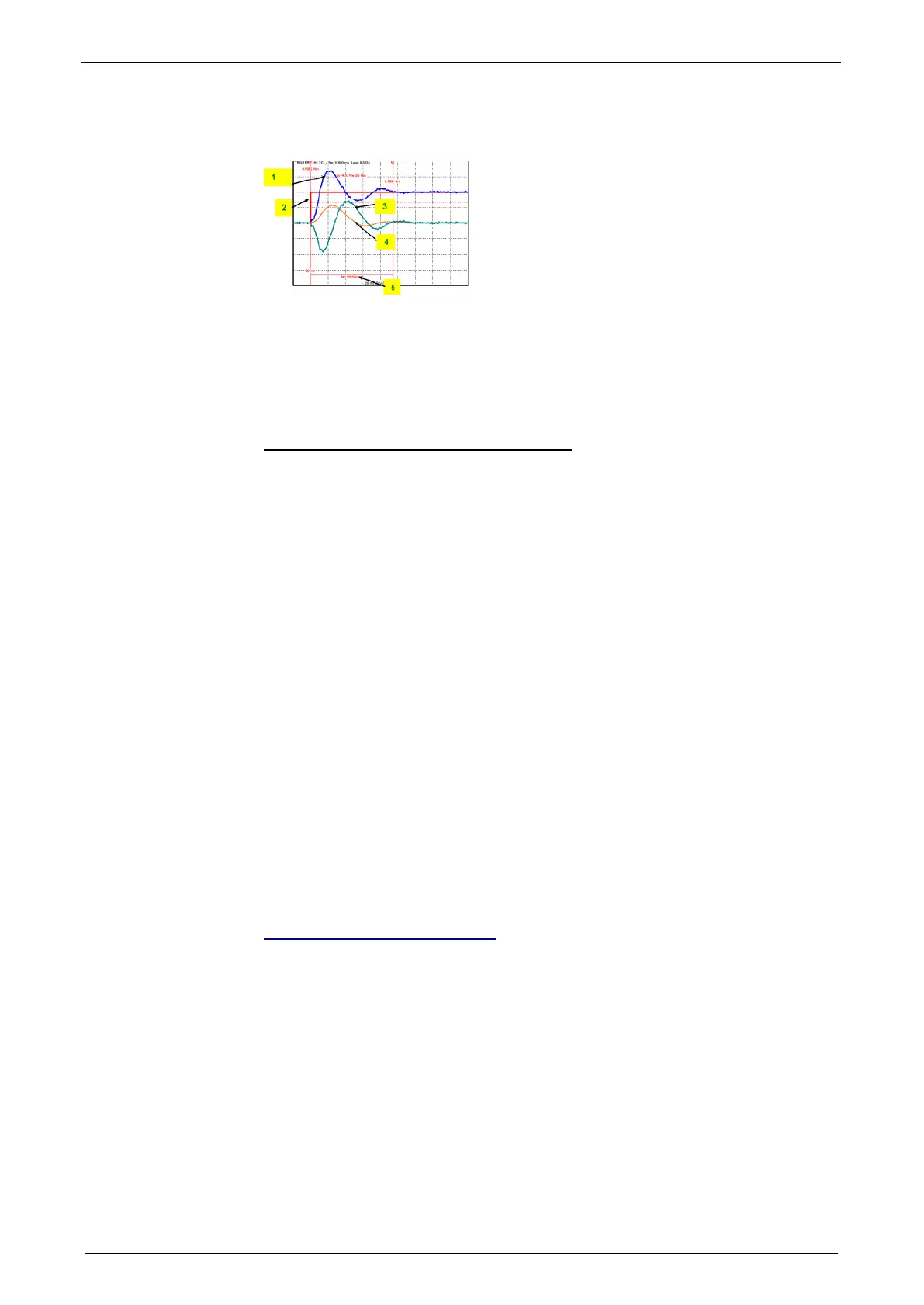
Disturbance jerk response
1: Compensation torque of the controller
2: Simulated disturbance torque
3: Actual speed
4: Following error
5: Settling Time
Correlation between the terms introduced
The introduced terms:
Stability
Damping
Velocity
Bandwidth
Setpoint and disturbance behavior
Control variable limitation
Replacement time constant
Rigidity
are related as follows:
A well-attenuated control features a stable control behavior.
The velocity of a control loop is a measure for the reaction rate of the controller to
the disturbance variable (disturbance behavior) as well as to the setpoint variable
(setpoint behavior).
The faster the control, the higher its bandwidth.
The term replacement time constant is an approximation and is only valid in a
defined scope1. In this scope, the control is always stable and well-attenuated.
If the controller does not work in the linear range, but the control variable of the
controller is within the limitation, the control slows down and the control difference
rises.
The stiffness represents the bandwidth of the velocity control. The higher the
stiffness value of the velocity control, the higher the bandwidth of the velocity
controller and the stiffer the drive.
Automated controller design
In this chapter you can read about:
Step response of the velocity loop depending on the optimization parameter "attenuation" and
"stiffness"....................................................................................................................... 203
D-term ........................................................................................................................... 203
Position loop .................................................................................................................. 203
The controller design takes place after the configuration immediately before the
configuration download into the device. The controller coefficients are preassigned
according to the design method of cross-ratios so that a stable control is achieved.
The automatic, robust controller design calculates the P and I terms of the
individual controllers (current, velocity, position) on the basis of the configured
motor and application parameters.