Parker EME
Setting up Compax3
192-120113 N08 C3I12T11 - December 2010
The frequency response shows the amplification (value) and the phase shift
(phase), which a signal is submitted to when passing through a system.
The displayed bode diagram allows the following conclusions:
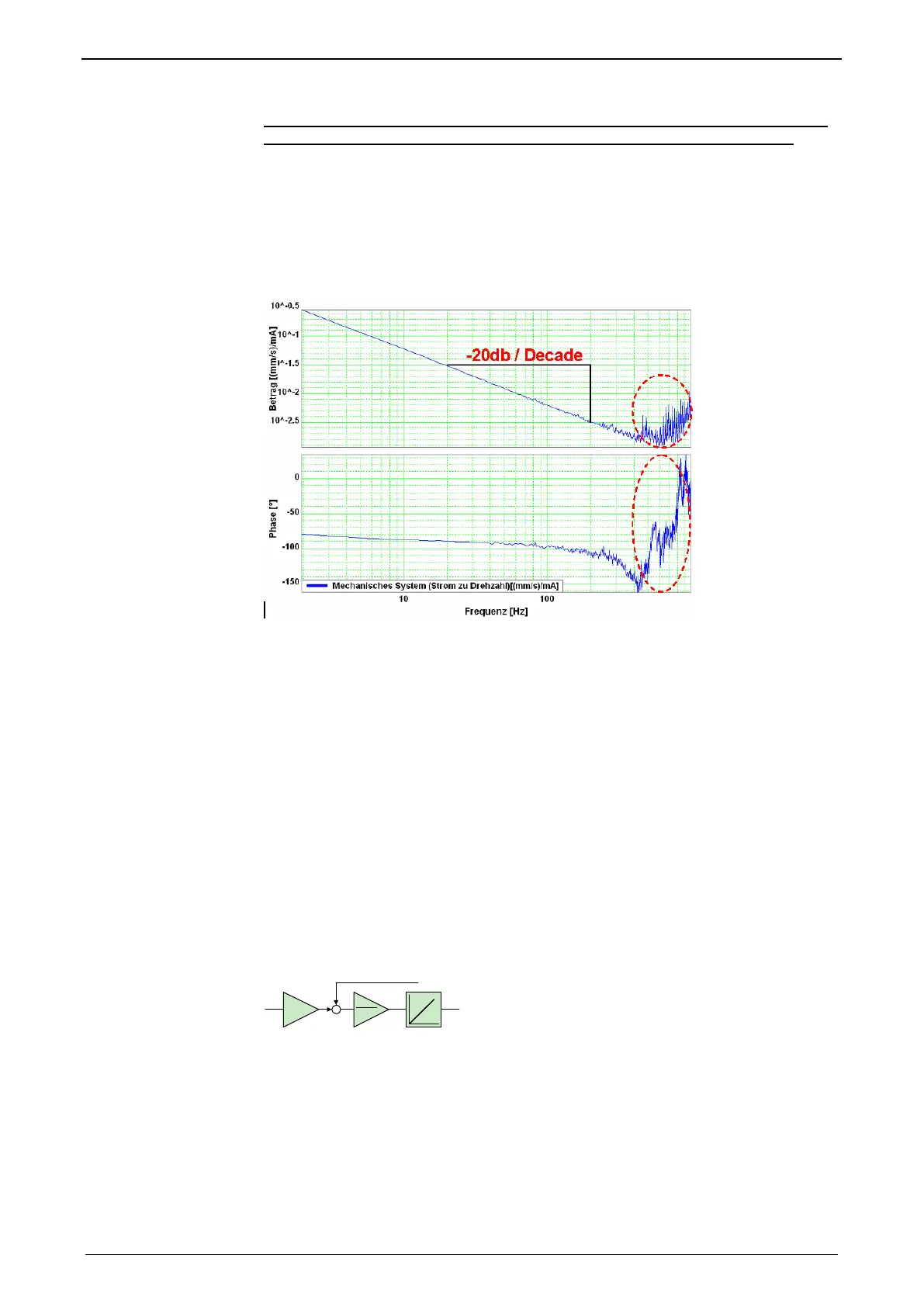
If a sine with 60Hz and an amplitude of 1A is present at the input, a sine delayed
by 94° and an amplitude of 0.01m/s will result at the output.
Mechanical system
Frequency response of a mechanic system: Current - velocity of a motor
The outlined course at the end of the measurement range does not permit
statements on the system measured due to disturbances. Due to the attenuation of
the signals increasing with the frequency, the sensitiveness of the measurement to
disturbances (signal to noise ratio) increases with a rising frequency. The value as
well as the phase response of the displayed frequency response are "disturbed" at
the same intensity, this shows, that disturbances are the reason.
The value response consists basically of a straight, which declines with a slope of -
20dB/decade (-20dB/decade => per tenfold increase of the frequency, the value
decreases also by factor ten.
The phase response remains however almost constantly at -90° over a relatively
large range.
In control technology, this is called integrating behavior (I-behavior).
the I-behavior can be explained as follows.
The measured current is proportional to the motor force and thus also to the
acceleration of the driven mass. As the velocity is calculated from the integrated
acceleration, the measured system looks as follows:
f: disturbance torque
Kt
2*Pi*J
1
velocity controlled
system
Input value is the current actual value, output value is the velocity actual value