3
9929399 R01 - 2018-2019 RANGER XP/ CREW 900/1000 Service Manual
© Copyright Polaris Industries Inc.
3.93
VALVE CLEARANCE ADJUSTMENT
NOTICE
Always inspect valve clearance prior to camshaft
installation or final engine assembly.
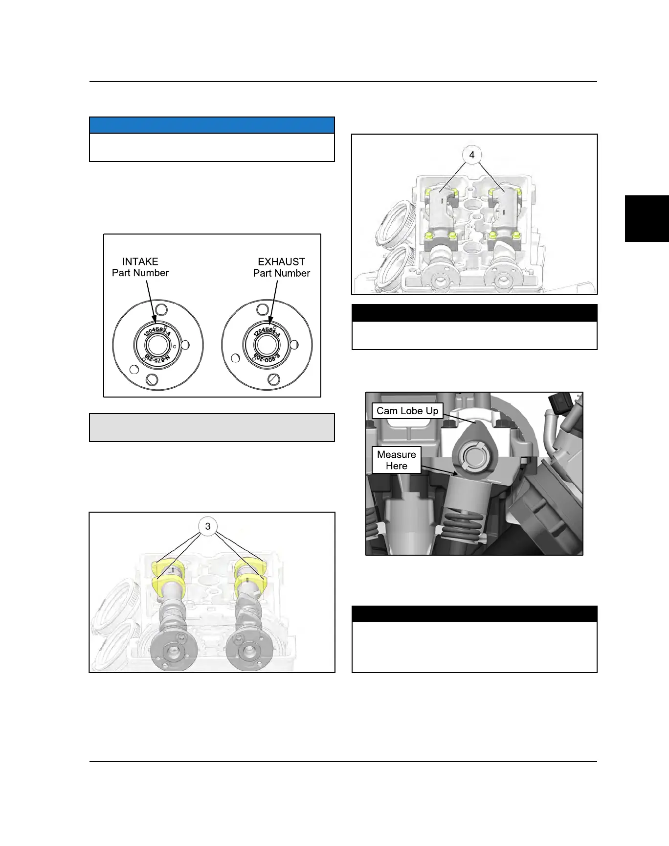
1. Reference the camshaft intake and exhaust
markings made during disassembly. If installing new
camshafts or if camshafts were not marked, you can
reference the part number stamped on the end of the
shafts.
Intake Camshaft PN: 1204583
Exhaust Camshaft PN: 1204584
2. Lubricate the camshaft bearing journal surfaces with
Polaris PS-4 engine oil prior to installation.
3. Carefully install the camshafts into the cylinder head.
The PTO camshaft lobes
e
should face out as
shown.
4. Carefully install the rear camshaft carriers onto the
camshafts. Carrier openings should face each other
when installed properly.
5. Install the four bolts that retain each rear camshaft
carrier
r
and tighten the bolts evenly to
specification.
TORQUE
Camshaft Carrier Bolts:
7 lb-ft (10 Nm)
6. Rotate the camshaft until the cam lobes above the
valves you are inspecting are facing up.
7. Measure the valve clearance using a thickness
(feeler) gauge. Record the measurement if clearance
is out of specification.
MEASUREMENT
Intake Valve Clearance (cold):
.006 ± .002 in. (0.15 ± 0.05 mm)
Exhaust Valve Clearance (cold):
.010 ± .002 in. (0.25 ± 0.05 mm)
8. Repeat steps 6 and 7 until all eight valves have been
inspected.
ENGINE / COOLING / HVAC SYSTEM
 Loading...