3.136
9929399 R01 - 2018-2019 RANGER XP/ CREW 900/1000 Service Manual
© Copyright Polaris Industries Inc.
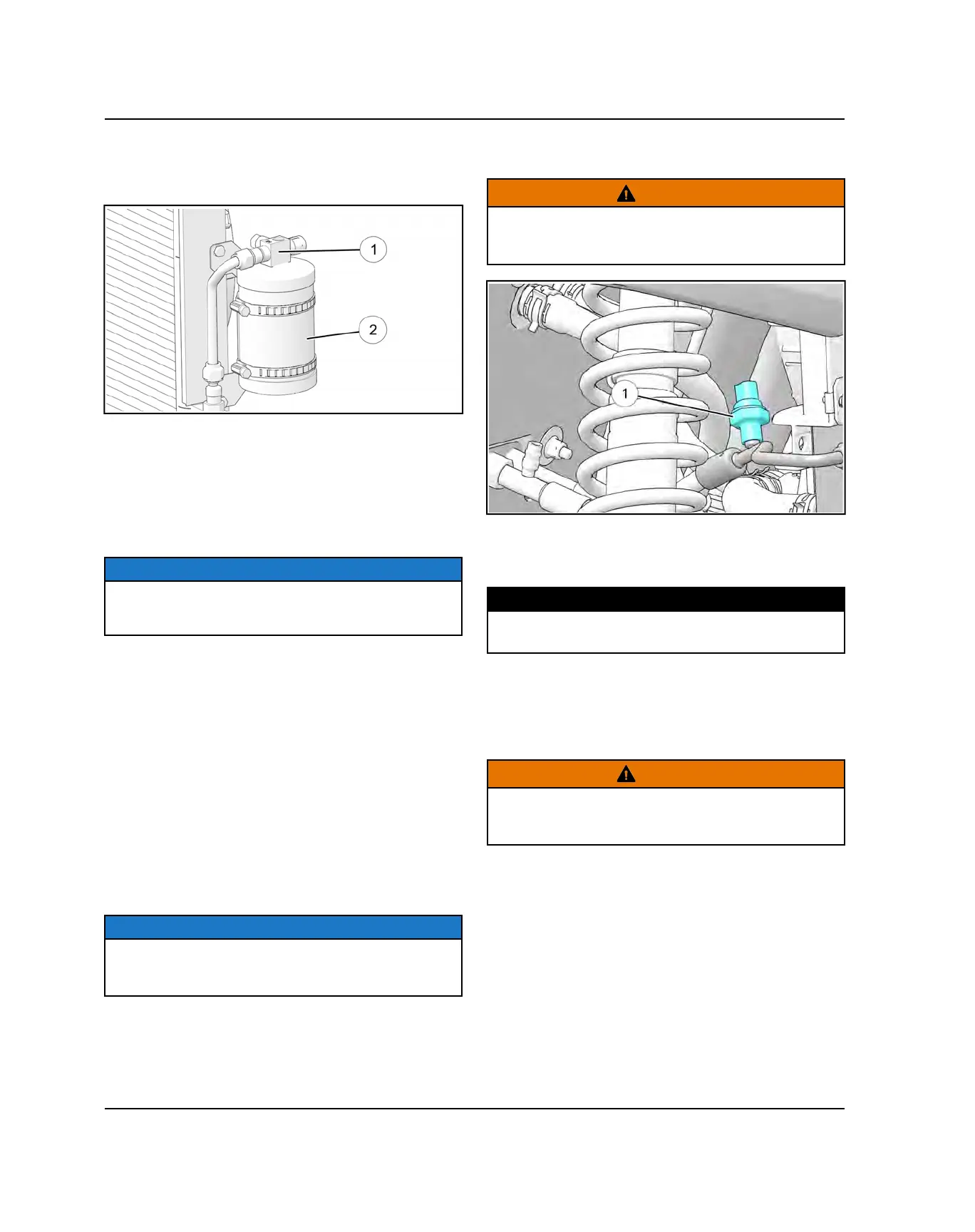
PRESSURE RELIEF VALVE REPLACEMENT
The pressure relief valve
q
is located on the receiver
drier assembly
w
.
The pressure relief valve is designed to open and
release the A/C charge if the pressure reaches 535 psi
(3.7 MPa).This will cause the A/C system to shut down,
saving the compressor.
The Pressure Relief Valve is a secondary protection
device in the A/C system, with the Pressure Switch
shutting down the system at 384 psi (2.6 MPa).
NOTICE
If a Pressure Relief Valve is found open, check the A/C
system for problems. Replace the complete receiver /
drier unit.
HIGH PRESSURE CUT-OUT (HPCO) SWITCH
OVERVIEW
Overview:
The HPCO switch will cycle the compressor off if
pressure is too high on the high pressure side.
Location:
The HPCO switch is located on the AC hose coming off
the receiver / drier.
HPCO SWITCH REPLACEMENT
NOTICE
Replacement of the high pressure cut out switch does
NOT require discharging/recharging the R-134a
refrigerant.
1. Disconnect the pressure switch connector
q
from
the wire harness.
WARNING
In the event of a leak, wear safety goggles. Escaping
refrigerant can cause severe injuries to eyes. In contact
with a flame, R-134a refrigerant gives a toxic gas.
2. Remove the pressure switch
w
.
3. Install pressure switch and torque the HPCO switch
to specification.
TORQUE
HPCO Switch:
6 ft-lb (8 Nm)
HEATER / EVAPORATOR UNIT REPLACEMENT
1. Remove the refrigerant from the A/C system.
WARNING
In the event of a leak, wear safety goggles. Escaping
refrigerant can cause severe injuries to eyes. In contact
with a flame, R-134a refrigerant gives a toxic gas.
2. Drain the cooling system. Refer to “Radiator
Removal / Coolant Drain”page 3.108 procedure.
3. Remove the upper and lower dash. Refer to “Dash
Panels / Glove Box Removal”page 10.30
procedure.
4. Disconnect the blower unit connector to the wire
harness.
ENGINE / COOLING / HVAC SYSTEM
 Loading...