5.26
9929399 R01 - 2018-2019 RANGER XP/ CREW 900/1000 Service Manual
© Copyright Polaris Industries Inc.
NOTICE
Spring is compression only and has no torsional wind.
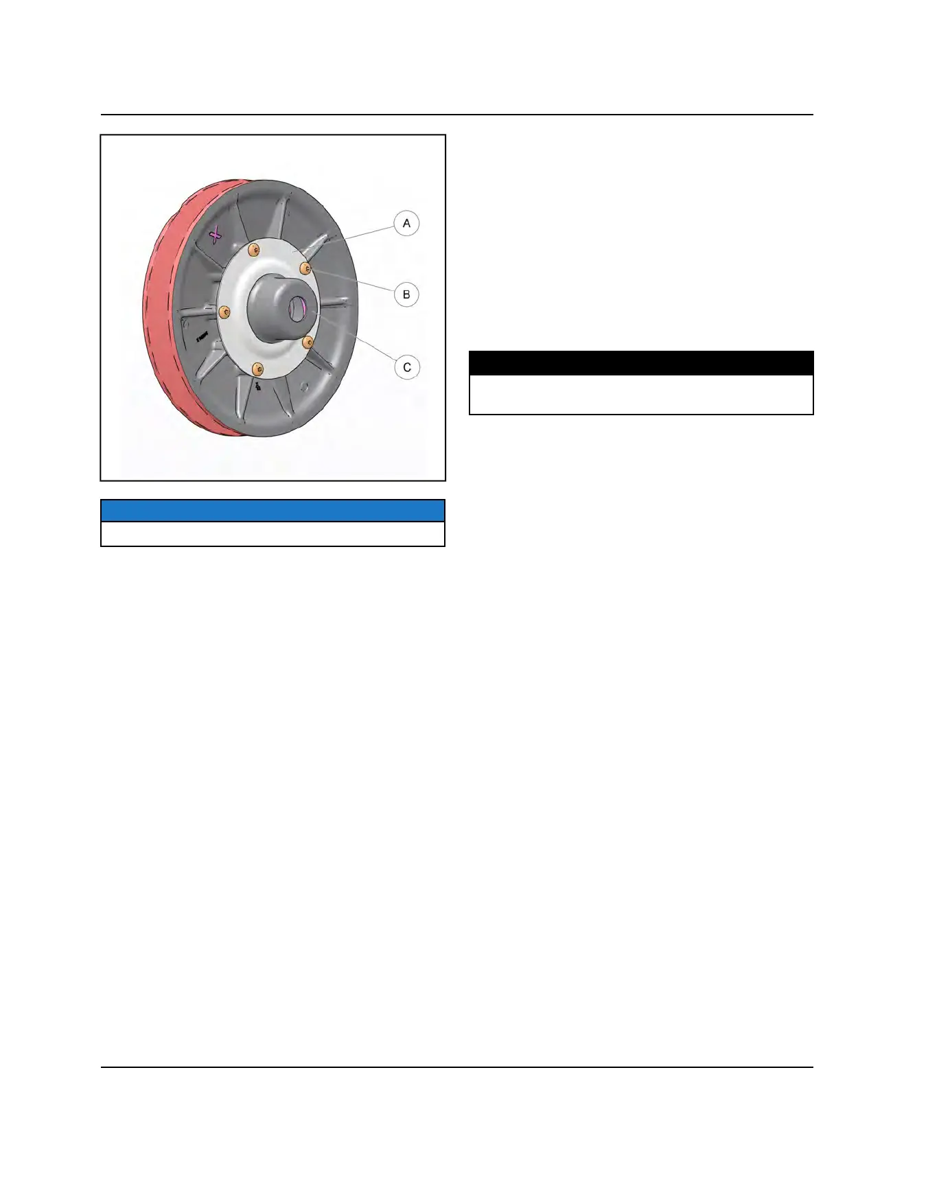
5. Turn the compressor tool handle counter-clockwise to
relieve spring pressure from the spring retainer plate and
spring cup.
6. Remove the compressor tool from the clutch.
7. Remove the cover plate (A), spring cup (C) and spring
from the inner clutch sheave.
8. Check the rollers in the stationary sheave for wear. If
rollers are worn, a new driven clutch assembly may be
needed.
9. Inspect the bearings inside the moveable sheave.
10. Inspect driven clutch sheave faces for wear or
damage.
11. Clean and inspect splines on helix and transmission
input shaft.
12. Lube splines with a light film of grease. Do not
lubricate the bearings!
CLUTCH ASSEMBLY (NON-EBS)
1. Align the reference or “X” marks on each of the
sheaves during reassembly.
2. Assemble the clutch sheaves.
3. Position the spring, spring cup and retaining plate into
moveable sheave. Do not apply oil or grease to the
bearings.
4. Place the clutch into the universal clutch compressor.
Apply and hold downward pressure on the spring cup.
Torque the retaining ring bolts to specification
Torque
TORQUE
Driven Clutch Retaining Ring Bolts:
9–12 lb-ft (12–16 Nm)
5. Install driven clutch assembly and drive belt.
PVT SYSTEM
 Loading...