Mounting the IDU-C Chapter 3
WinLink 1000 User Manual Release 1.9.40 3-10
IDU-R Installation
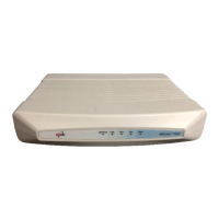
Figure 3-12: IDU-R Rear Panel
Installation of an IDU-R unit differs from other IDU models in one respect: At the rear of the
IDU-R (see Figure 3-12) there are two jacks labeled “Trunks”. For each IDU-R, the E1 cable
from outside should be plugged into one of the trunks, and the E1 cable to the other station
should be plugged into the second trunk, as in the left hand side of Figure 1-12.
Apart from the above difference, the link installation including the remaining part of the IDU
installation and connection to the ODU proceeds as described as above.
Mounting the IDU-C
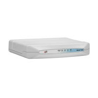
IDU-Cs are all rack mountable, as shown in Figure 3-13. A front panel keyed schematic of a
rack mounted IDU-C is shown in the figure below.
Figure 3-13: IDU-C front panel
Further description of the keyed items in Figure 3-13 is shown in Table 3-1 below:
Table 3-1: Components of an IDU-C front panel
Key Label Remarks
A Indicator LEDs See Figure 3-14.
B ODU Port RJ-45 connector, see Table B-1.
C LAN RJ45Ports Ethernet, RJ-45 connector, see Table B-3.
D LAN SFP Port See Appendix C.
E Alarm Ports Standard DB25 female connector, see Table B-7.
F Label indent Place for adhesive identification labels.
 Loading...